1994 Ford Probe PCM Wiring Diagram - CKP & ECT Sensor, TCM Circuits (Page 5)

Reference · 1993-1997 ProbeAll 65 wiring diagrams
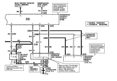
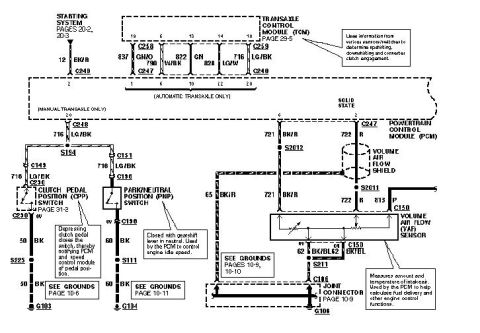
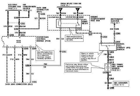
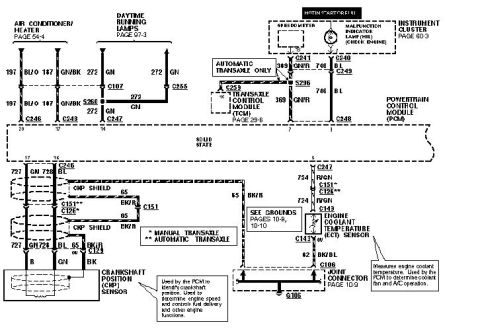
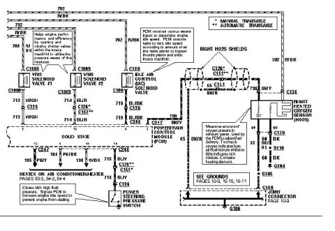
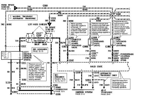
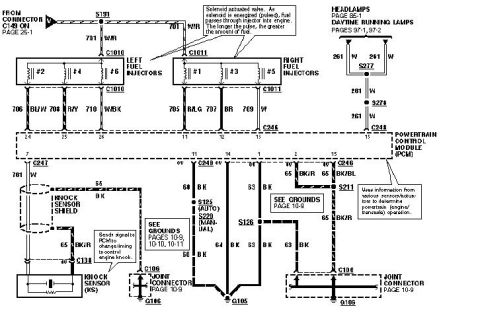
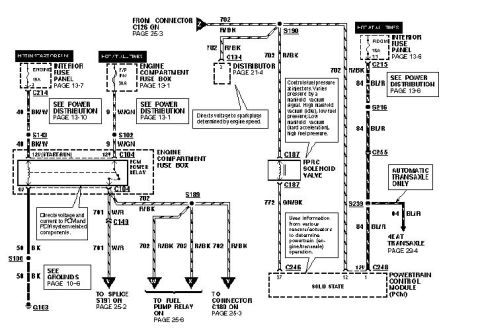









Ford wiring diagram showing the crankshaft position sensor, engine coolant temperature sensor and PCM with color-coded wires and connectors.
Part of 1993-1997 Ford Probe Wiring Diagrams
This document is one page of a multi-page Powertrain Control Module (PCM) wiring diagram for a Ford Probe. It shows circuits connecting the PCM to the Air Conditioner/Heater (page 54-4), Daytime Running Lamps (page 97-3), and the Instrument Cluster (page 60-3) including the speedometer and Malfunction Indicator Lamp (MIL/Check Engine). For automatic transaxle vehicles, circuit 369 GN/R and 746 BL link the PCM to the Transaxle Control Module (TCM, page 29-6) through connectors C241, C240, C249, C259, S296, and C248. The lower half details the Crankshaft Position (CKP) Sensor wiring, circuits 727 GN and 728 BL with a shielded circuit 65 BK/R through connectors C246, C151, C126, and C123, and the Engine Coolant Temperature (ECT) Sensor wiring, circuit 724 R/GN through C247 and C143, grounding via circuit 62 BK/BL through joint connector C106 to ground G106 (grounds referenced on pages 10-8 and 10-10). Notes explain the CKP sensor identifies crankshaft position for engine speed and fuel delivery control, while the ECT sensor's reading is used by the PCM for coolant fan and A/C operation. Legend marks distinguish manual (*) versus automatic (**) transaxle connector usage. Wire colors include GN, BL, BK/R, R/GN, GN/BK, BL/O, GN/R, and BK/BL.
Is this accurate? Sign in to help verify it.
Frequently asked questions
- What circuits connect the PCM to the Crankshaft Position (CKP) sensor?
- Circuits 727 GN and 728 BL, with a shielded ground circuit 65 BK/R, routed through connectors C246, C151/C126, and C123 to the CKP sensor.
- How is the Engine Coolant Temperature (ECT) sensor wired to the PCM?
- Circuit 724 R/GN runs from the PCM through connector C247 to the ECT sensor at C143, and the sensor grounds via circuit 62 BK/BL through joint connector C106 to ground G106.
- What does the PCM use the ECT sensor signal for according to this diagram?
- The note states the ECT sensor measures engine coolant temperature and is used by the PCM to determine coolant fan and A/C operation.
- Which circuits connect the PCM to the Transaxle Control Module (TCM)?
- On automatic transaxle vehicles only, circuit 369 GN/R and circuit 746 BL connect through connectors C241, C240, C249, C259, S296, and C248 to the TCM (page 29-6).
- What do the asterisk marks on connectors C151 and C126 mean?
- A single asterisk (*) means manual transaxle and a double asterisk (**) means automatic transaxle, indicating which connector applies to each transmission type.






No comments yet.