1993-94 Ford Probe PCM Wiring Diagram - VAF Sensor, CPP & PNP Switch Circuits
Reference · 1993-1997 ProbeAll 65 wiring diagrams
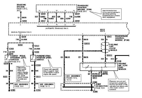
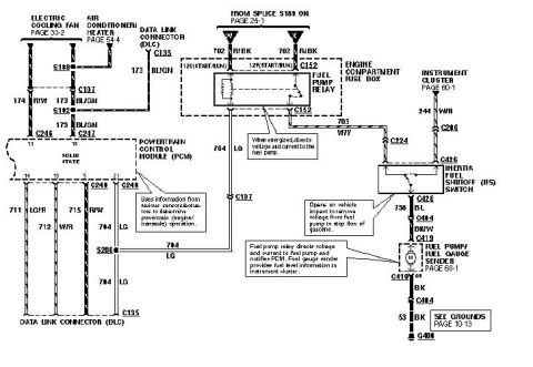
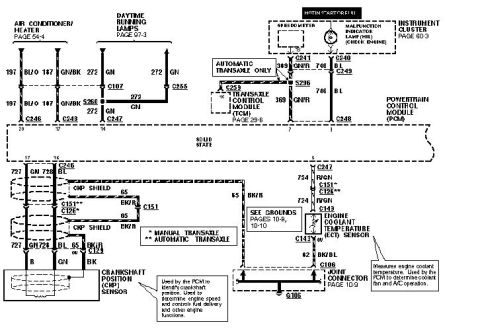
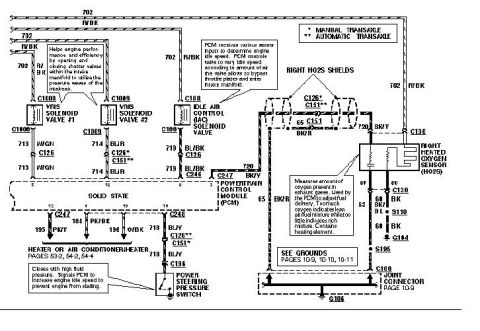
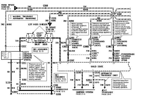









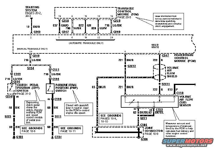
Ford wiring diagram showing the clutch pedal position switch, park/neutral position switch and volume air flow (VAF) sensor to the PCM.
Part of 1993-1997 Ford Probe Wiring Diagrams
This scanned wiring diagram page (uploaded as '94 ecu page 7' for a Ford Probe) shows Powertrain Control Module (PCM) input circuits and related connections. The top of the page shows the Transaxle Control Module (TCM, page 29-5) with wires 837 GN/O, 790, 822 W/BK, 828 GN, and 716 LG/W passing through connectors C248/C247/C259 on automatic transaxle vehicles; a callout explains the TCM uses sensor/switch information to determine upshifting, downshifting, and converter clutch engagement. For manual transaxles, circuit 716 LG/BK feeds the Clutch Pedal Position (CPP) switch at C230 (page 31-2), which closes when the clutch pedal is depressed to notify the PCM and speed control module. The Park/Neutral Position (PNP) switch at C156 closes with the gearshift in neutral so the PCM can control idle speed. Both switches ground through circuits 50 BK (S225, G103) and 60 BK (S111, G104). The right side shows the Volume Air Flow (VAF) sensor at C150 with circuits 721 BK/R, 722 R, 65 BK/R, and 813 P, a shielded harness (Volume Air Flow Shield), splices S2011/S2012, and grounding through 62 BK/BL, S211, and joint connector C106 to G106. Ground references cite pages 10-6, 10-9, 10-10, and 10-11.
Is this accurate? Sign in to help verify it.
Frequently asked questions
- What does the Volume Air Flow (VAF) sensor do on the Ford Probe?
- Per the diagram callout, the VAF sensor (connector C150) measures the amount and temperature of intake air, which the PCM uses to help calculate fuel delivery and other engine control functions.
- What wire colors connect to the VAF sensor?
- Circuits shown at the VAF sensor are 65 BK/R, 721 BK/R, 722 R, and 813 P, with a shielded section (Volume Air Flow Shield) and ground circuit 62 BK/BL through splice S211 and joint connector C106 to ground G106.
- What does the Clutch Pedal Position (CPP) switch do?
- Depressing the clutch pedal closes the switch (connector C230, circuit 716 LG/BK), thereby notifying the PCM and speed control module of pedal position. It grounds via circuit 50 BK through S225 to G103.
- What is the Park/Neutral Position (PNP) switch used for?
- The PNP switch (connector C156) is closed with the gearshift lever in neutral and is used by the PCM to control engine idle speed. It grounds via circuit 60 BK through S111 to G104.
- Which circuits run between the TCM and PCM on automatic transaxle models?
- The automatic-transaxle-only section shows circuits 837 GN/O, 790, 822 W/BK, 828 GN, and 716 LG/W between the TCM (page 29-5) and the PCM through connectors C248, C247, and C259.






No comments yet.