1994 Ford Probe PCM Wiring Diagram - TP Sensor, EVP Sensor & TCM Circuits
Reference · 1993-1997 ProbeAll 65 wiring diagrams
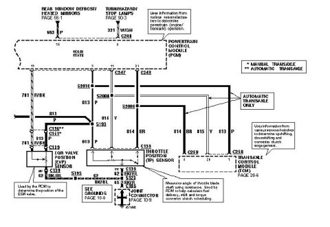
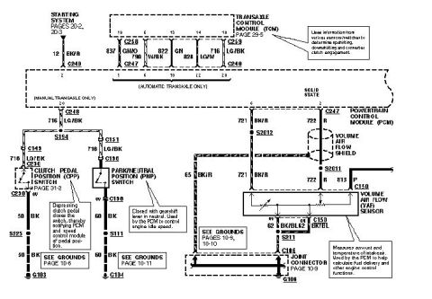
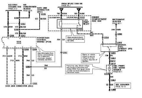
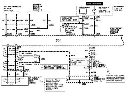
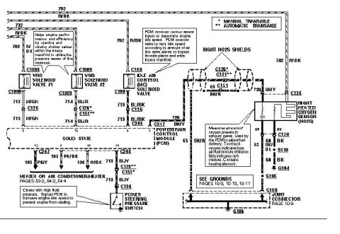









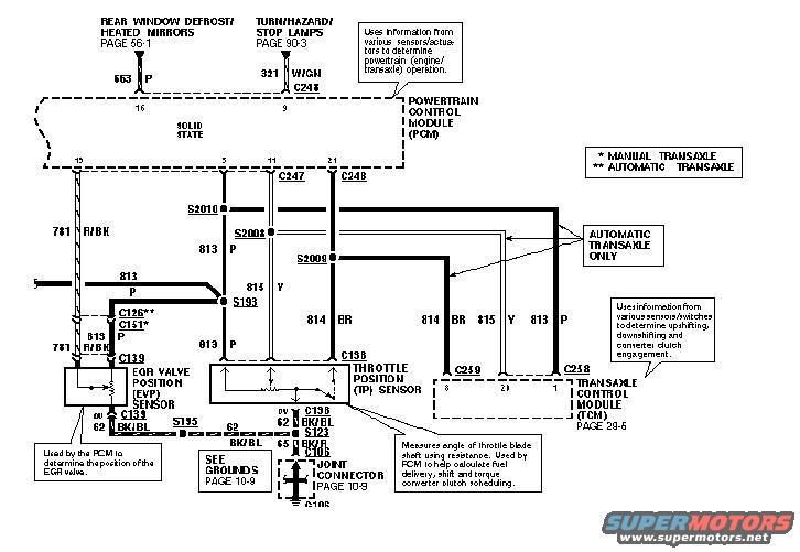
Ford wiring diagram showing the EGR valve position (EVP) sensor and throttle position (TP) sensor connecting to the PCM and transaxle control module.
Part of 1993-1997 Ford Probe Wiring Diagrams
This is one page of a multi-page factory-style wiring diagram set showing the Powertrain Control Module (PCM) circuits, apparently for a mid-1990s Ford Probe (uploaded as '94 ecu page 8'). The diagram shows the PCM (solid state) with connectors C247 and C248, and its interfaces with the EGR Valve Position (EVP) Sensor via connector C139 and the Throttle Position (TP) Sensor via connector C138. Sensor reference and signal wires include circuit 781 (R/BK), 813 (P), 815 (Y), and 814 (BR), with splices S2008, S2009, S2010, S193, S195, and S123 shown. Ground paths use circuits 62 (BK/BL) and 65 (BK/R) through joint connector C106 to ground G106 (see Grounds, page 10-9). Automatic-transaxle-only branches route TP and reference signals to the Transaxle Control Module (TCM) via connectors C259 and C258 (TCM detail on page 29-5); connectors C126 (automatic) and C151 (manual) are footnoted. Cross-references at the top point to Rear Window Defrost/Heated Mirrors (page 56-1, circuit 553 P) and Turn/Hazard/Stop Lamps (page 90-3, circuit 321 W/GN). Callouts explain that the TP sensor measures throttle blade angle for fuel delivery and shift/torque converter clutch scheduling, and that the TCM controls upshifting, downshifting and converter clutch engagement.
Is this accurate? Sign in to help verify it.
Frequently asked questions
- What wire colors connect the PCM to the Throttle Position sensor on this diagram?
- The TP sensor (connector C138) uses circuit 813 P (reference), 814 BR (signal), and grounds through 62 BK/BL; circuit 815 Y also appears in the sensor reference/return network.
- What does the Throttle Position (TP) sensor do according to this diagram?
- It measures the angle of the throttle blade shaft using resistance and is used by the PCM to help calculate fuel delivery, shift and torque converter clutch scheduling.
- Which connectors go to the Transaxle Control Module (TCM)?
- Connectors C259 (pins 8 and 20) and C258 (pin 1) route to the TCM, shown on page 29-5, and this branch is marked 'Automatic Transaxle Only'.
- How is the EVP sensor grounded?
- The EGR Valve Position sensor grounds through circuit 62 BK/BL via splice S195, then through S123 and circuit 65 BK/R to joint connector C106 and ground G106 (see Grounds, page 10-9).
- What do the asterisks (* and **) mean on this diagram?
- A single asterisk (*) denotes manual transaxle (e.g., C151*) and a double asterisk (**) denotes automatic transaxle (e.g., C126**).






No comments yet.