Ford Probe Instrument Cluster Wiring Diagram - Tachometer & Oil Pressure Gauge

Reference · 1993-1997 ProbeAll 65 wiring diagrams
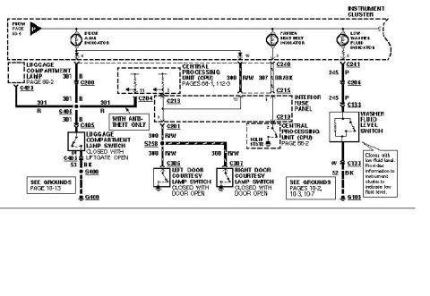
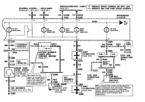
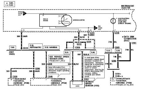
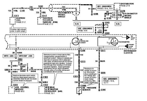
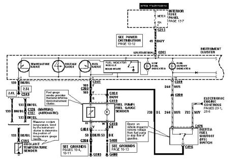
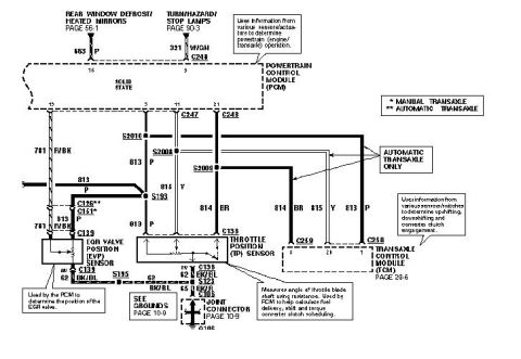
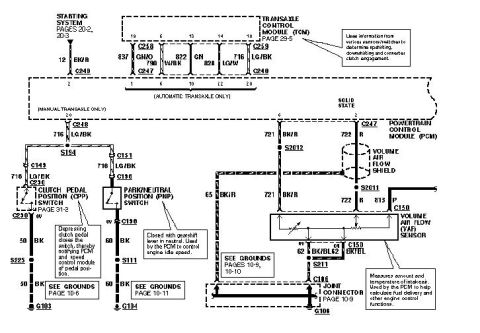
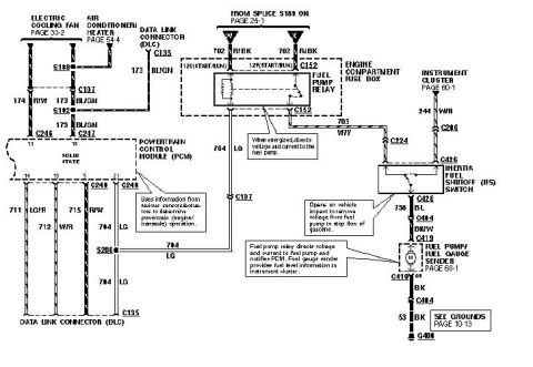









Ford wiring diagram showing the ignition coil, tachometer, internal alternator regulator, oil pressure gauge and sender with color-coded wires.
Part of 1993-1997 Ford Probe Wiring Diagrams
This document is a scanned wiring diagram page covering the instrument cluster tachometer and oil pressure gauge circuits for a Ford Probe, with separate ignition input paths shown for the 2.0L engine (ignition coil C171 and Ignition Control Module ICM at C147, page 21-3) and the 2.5L engine (distributor, page 21-5). The tachometer signal travels on circuit 731 Y/BL inside a shielded cable (Tachometer Signal Shield) with shield drains 60/61 BK to ground G106. The oil pressure gauge feeds through connectors C240, C255, and C126 on circuit 110 P/Y down to the oil pressure sender at C1000; a note explains sender resistance increases as oil pressure drops, producing little meter movement. The charge indicator/alternator circuit (20 W/BK) runs through C206, splice S2014, C180, and C153 to the Internal Alternator Regulator (IAR, page 12-1), with a WITH ABS/WITHOUT ABS split routing to the ABS Control Module at C223 (page 42-2). The tachometer grounds through C241 on 59 BK/R via splice S228 to G105. Cross-references include grounds pages 10-4, 10-8, 10-9, and 10-11. Readers can trace wire colors, circuit numbers, connectors, splices, and grounds for cluster diagnosis.
Is this accurate? Sign in to help verify it.
Frequently asked questions
- What wire carries the tachometer signal in this diagram?
- Circuit 731 Y/BL (yellow/blue) carries the tachometer signal, routed inside a Tachometer Signal Shield. On the 2.0L it comes from the ignition coil (C171) and Ignition Control Module (C147); on the 2.5L it comes from the distributor via C170.
- What connectors are in the oil pressure gauge circuit?
- The oil pressure gauge circuit runs on wire 110 P/Y from cluster connector C240 through C255 and C126 to C1000 at the oil pressure sender.
- How does the oil pressure sender work according to this diagram?
- Per the callout, resistance in the sender increases as oil pressure drops, resulting in low voltage and current at the instrument cluster and producing little meter movement.
- Where does the tachometer ground?
- Through connector C241 on wire 59 BK/R, via splice S228 to ground G105 (see grounds pages 10-4, 10-11).
- What does the 20 W/BK wire connect to?
- The 20 W/BK circuit runs from the instrument cluster through C206 and splice S2014, splitting for WITH ABS (to C223, ABS Control Module, page 42-2) and continuing through C180 and C153 to the Internal Alternator Regulator (IAR), page 12-1.






No comments yet.