1994 Ford Probe Instrument Cluster Wiring Diagram - Fuel & Temp Gauge Circuits
Reference · 1993-1997 ProbeAll 65 wiring diagrams
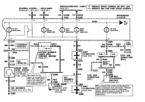
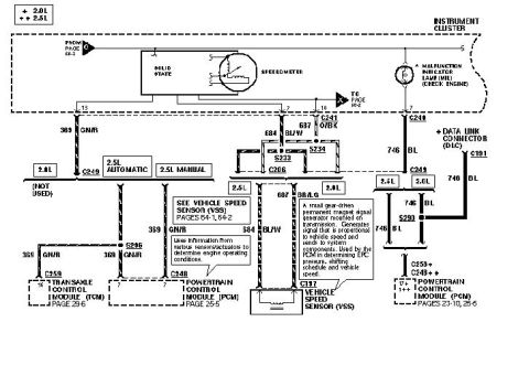
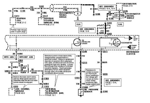
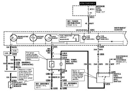
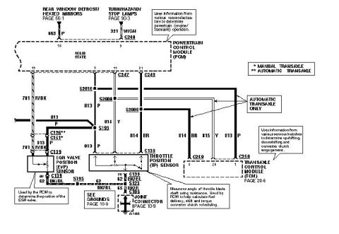
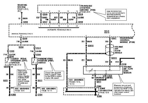
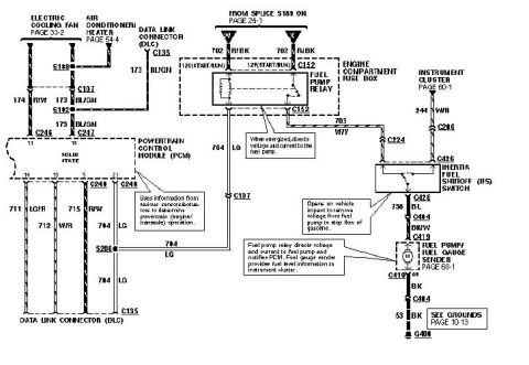
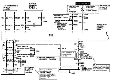









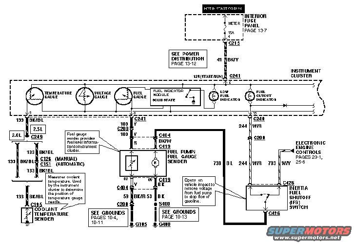
Ford wiring diagram showing instrument cluster gauges, the fuel pump/fuel gauge sender, coolant temperature sender and inertia fuel shutoff switch.
Part of 1993-1997 Ford Probe Wiring Diagrams
This document is a scanned automotive wiring diagram covering the instrument cluster fuel and temperature gauge circuits, applicable to a vehicle offered with 2.0L and 2.5L engines (consistent with a mid-1990s Ford Probe). Power feeds from the interior fuse panel (METER 15A fuse, hot in start or run, page 13-7) through connector C213 on circuit 41 BK/Y to the instrument cluster at connector C241 (12V start/run). The cluster contains the temperature gauge, voltage gauge, fuel gauge, a solid-state fuel indicator module, a low fuel indicator, and a fuel cutout indicator. The fuel pump/fuel gauge sender connects via connectors C404 and C419 with circuits 103 Y/R and BK/W, grounding through 59 BK/R and 53 BK to grounds G105 and G400 (splice S400). The coolant temperature sender (C185) feeds the temperature gauge via circuit 133 BK/BL, routing through C249 and C126 (manual) or C151 (automatic). The inertia fuel shutoff (IFS) switch at C426 opens on vehicle impact to cut voltage to the fuel pump; circuits 738 BL, 244 W/R, and 703 W/Y tie into the electronic engine controls (pages 23-1, 25-6). Callouts explain sender and IFS switch functions, and ground/power distribution page references are included.
Is this accurate? Sign in to help verify it.
Frequently asked questions
- What fuse powers the instrument cluster gauges in this diagram?
- The METER 15A fuse in the interior fuse panel (page 13-7), which is hot in start or run, feeds the cluster through connector C213 on circuit 41 BK/Y.
- What does the inertia fuel shutoff (IFS) switch do?
- Per the callout, it opens on vehicle impact to remove voltage from the fuel pump to stop the flow of gasoline. It connects at connector C426.
- How does the temperature gauge get its signal?
- The coolant temperature sender (connector C185) measures coolant temperature on circuit 133 BK/BL; the instrument cluster uses this to determine the position of the temperature gauge needle. The circuit routes through C249 and either C126 (manual) or C151 (automatic).
- Which connectors serve the fuel pump/fuel gauge sender?
- The fuel pump/fuel gauge sender connects through connectors C404 and C419, with grounds via 59 BK/R and 53 BK wires to splice S400 and grounds G105 and G400.
- What indicators are part of the instrument cluster in this diagram?
- The cluster includes the temperature gauge, voltage gauge, fuel gauge, a solid-state fuel indicator module, a low fuel indicator, and a fuel cutout indicator.






No comments yet.