Ford Probe Instrument Cluster & VSS Wiring Diagram - 2.0L/2.5L Speedometer

Reference · 1993-1997 ProbeAll 65 wiring diagrams
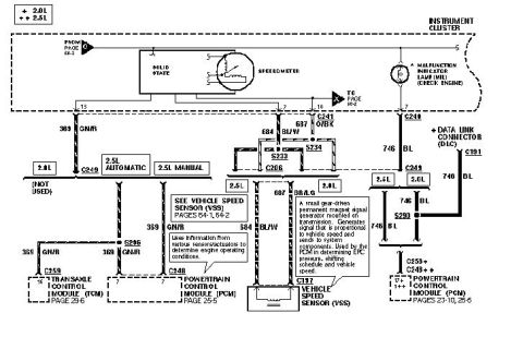
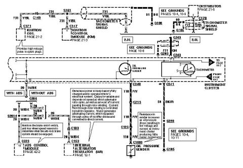
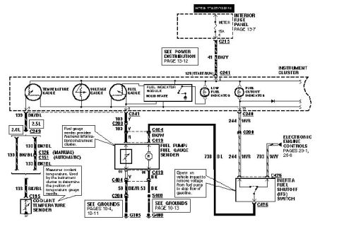
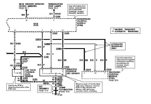
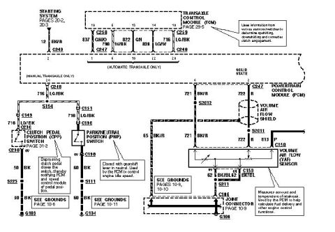









Ford wiring diagram showing the speedometer, vehicle speed sensor (VSS) and connections to the PCM and transaxle control module.
Part of 1993-1997 Ford Probe Wiring Diagrams
This document is one page of a factory-style wiring diagram covering the instrument cluster speedometer and vehicle speed sensor (VSS) circuits for a Ford Probe with either the 2.0L or 2.5L engine (legend: * = 2.0L, ** = 2.5L). It shows the solid-state speedometer within the instrument cluster, the malfunction indicator lamp (MIL/Check Engine), and the Data Link Connector (DLC). Circuit wiring is identified by number and color: circuit 359 GN/R (green/red) from cluster pin 13, circuit 684 BL/W (blue/white) from pin 7, circuit 687 O/BK (orange/black) through connector C241, circuit 687 BR/LG for the 2.5L, and circuit 746 BL feeding the DLC. Connectors and splices shown include C249, C246, C241, C206, C191, C259, C248, C258, C197, and splices S233, S234, S290, S296. Branches differ between 2.0L, 2.5L automatic, and 2.5L manual configurations. Callout notes explain that the VSS is a small gear-driven permanent magnet signal generator on the transmission used by the PCM for EPC pressure, shift scheduling, and vehicle speed, and that the PCM uses sensor inputs to determine engine operating conditions. Cross-references point to VSS pages 64-1/64-2, TCM page 29-6, and PCM pages 23-10 and 25-5.
Is this accurate? Sign in to help verify it.
Frequently asked questions
- What wire color is the vehicle speed sensor signal to the speedometer?
- Circuit 684 BL/W (blue/white) runs from the vehicle speed sensor (C197) up to pin 7 of the instrument cluster, and circuit 359 GN/R connects at pin 13.
- What circuit feeds the Data Link Connector (DLC) in this diagram?
- Circuit 746 BL (blue) runs through connector C191 and splice S290 to the Data Link Connector.
- What does the callout say about the vehicle speed sensor?
- It is a small gear-driven permanent magnet signal generator mounted on the transmission. It generates a signal proportional to vehicle speed and sends it to system components; the PCM uses it to determine EPC pressure, shift schedule, and vehicle speed.
- Which modules are connected in this circuit and where are their diagrams?
- The Transaxle Control Module (TCM) via C259 pin 16 (page 29-6) and the Powertrain Control Module (PCM) via C248/C258 (pages 25-5 and 23-10).
- Does the wiring differ between engines?
- Yes. The legend marks * for 2.0L and ** for 2.5L, with separate branches for the 2.0L (one marked 'not used'), 2.5L automatic, and 2.5L manual; the 2.5L uses circuit 687 BR/LG.






No comments yet.