1994 Ford Probe Instrument Cluster Wiring Diagram - Warning Indicators & Air Bag
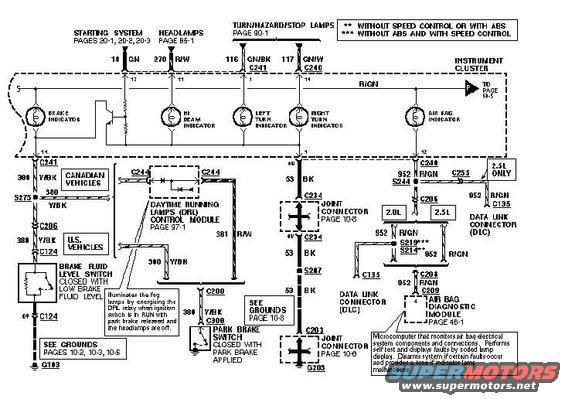
Ford wiring diagram showing instrument cluster warning indicators, brake fluid level switch, park brake switch and air bag diagnostic module.
This document is one page of a factory-style wiring diagram (EVTM) for the instrument cluster warning indicator circuits, uploaded as '94 cluster 4' for a Ford Probe. It shows the brake, hi beam, left turn, right turn, and air bag indicator lamps within the instrument cluster and their supporting circuits. Feeds come from the starting system (circuit 18 GN, pages 20-1 to 20-3), headlamps (270 R/W, page 95-1), and turn/hazard/stop lamps (116 GN/BK and 117 GN/W via connectors C241 and C240, page 90-1). The brake indicator circuit (300/380 Y/BK) differs between Canadian and U.S. vehicles, running through the brake fluid level switch (closed with low brake fluid), the park brake switch (closed with park brake applied), and the Daytime Running Lamps (DRL) control module (page 97-1) on Canadian vehicles, grounding at G103. Ground circuit 53 BK runs through joint connectors C234 and C203 to G203. The air bag indicator circuit 952 R/GN connects to the Air Bag Diagnostic Module (page 46-1) and the Data Link Connector (DLC) at C135, with splices S219/S214 varying by speed control/ABS equipment and connector routing differing between 2.0L and 2.5L engines. Notes explain DRL relay operation and air bag module self-test behavior.
Is this accurate? Sign in to help verify it.
Frequently asked questions
- What wire color is the air bag indicator circuit on this cluster diagram?
- Circuit 952 R/GN (red/green), running from the air bag indicator through splice S244 and connectors C240/C255 to the Air Bag Diagnostic Module (C208/C209) and the Data Link Connector (DLC) at C135.
- When does the brake fluid level switch close?
- The brake fluid level switch closes with low brake fluid level; it is in the brake indicator circuit through connector C124 and grounds at G103.
- How does the brake indicator circuit differ between U.S. and Canadian vehicles?
- Canadian vehicles use circuit 300 Y/BK through C241 and route through the Daytime Running Lamps (DRL) control module; U.S. vehicles use circuit 380 Y/BK through C206 and C124.
- What does the DRL control module do according to this diagram?
- It illuminates the fog lamps by energizing the DRL relay when the ignition switch is in RUN with the park brake released and the headlamps off. Its circuit is covered on page 97-1.
- Where does the instrument cluster ground circuit 53 BK terminate?
- Circuit 53 BK runs through joint connectors C234 and C203 (page 10-6) and splice S207 to ground G203; see grounds page 10-8.
Comments
More from this build



No comments yet.