Ford Probe Instrument Cluster Connector C240 Pinout - Wire Colors & Functions

Reference · 1993-1997 ProbeAll 65 wiring diagrams
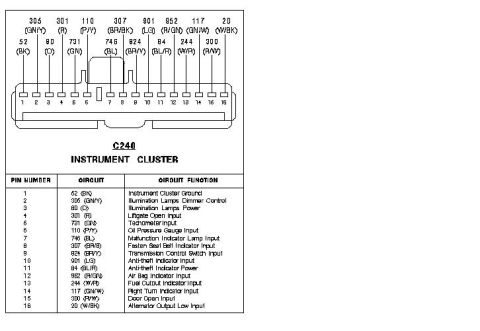
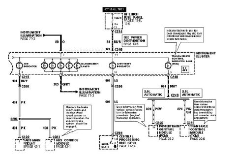
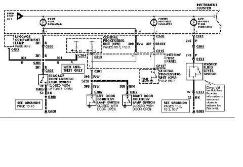
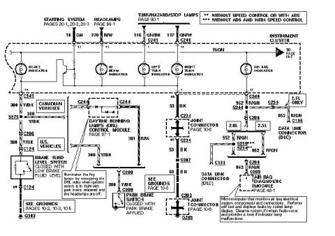
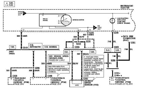









Wiring diagram of the C240 instrument cluster connector listing each pin's circuit, wire color code, and function.
Part of 1993-1997 Ford Probe Wiring Diagrams
This document is a connector pinout diagram for connector C240, which plugs into the instrument cluster. It shows a 16-pin connector drawing with each cavity numbered 1 through 16 and labeled with its circuit number and wire color code (e.g., 305 GN/Y, 52 BK, 20 W/BK). Below the drawing, a three-column table lists each pin number, its circuit designation with wire color, and the circuit function. Functions covered include instrument cluster ground (pin 1), illumination lamp dimmer control and power (pins 2-3), liftgate open input (pin 4), tachometer input (pin 5), oil pressure gauge input (pin 6), malfunction indicator lamp input (pin 7), fasten seat belt indicator input (pin 8), transmission control switch input (pin 9), anti-theft indicator input and power (pins 10-11), air bag indicator input (pin 12), fuel cutout indicator input (pin 13), right turn indicator input (pin 14), door open input (pin 15), and alternator output low input (pin 16). A reader can use this document to identify which wire and color corresponds to each instrument cluster signal for diagnosis, gauge or indicator troubleshooting, or cluster swap wiring work.
Is this accurate? Sign in to help verify it.
Frequently asked questions
- What is connector C240?
- C240 is a 16-pin instrument cluster connector; the diagram shows each pin's circuit number, wire color, and function.
- Which pin on C240 is the tachometer input?
- Pin 5, circuit 731 with a GN (green) wire, is the Tachometer Input.
- What wire is the instrument cluster ground on C240?
- Pin 1, circuit 52 with a BK (black) wire, is the Instrument Cluster Ground.
- Which C240 pin carries the oil pressure gauge signal?
- Pin 6, circuit 110 with a P/Y (purple/yellow) wire, is the Oil Pressure Gauge Input.
- What pin controls the illumination lamps dimming?
- Pin 2, circuit 305 (GN/Y), is Illumination Lamps Dimmer Control; pin 3, circuit 80 (O), is Illumination Lamps Power.






No comments yet.