1994 Ford Probe 2.5L Condenser Fan & A/C Clutch Wiring Diagram
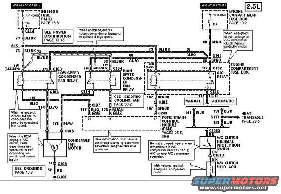
Wiring diagram showing the 2.5L A/C clutch and cooling fan relay circuits with color-coded wires and connectors.
This document is a factory-style wiring diagram for the condenser fan and A/C clutch circuits on a 2.5L engine (uploaded as a 1994 Ford Probe reference). Power comes from two sources: an AIR-COND 15A fuse in the interior fuse panel (hot in ACC or RUN, feeding circuit 73 BL/BK through connector C214 and splice S151) and an AIR-COND 40A fuse in the engine compartment fuse box (hot at all times, feeding circuit 88 GN/O through splice S141). The diagram shows the low speed condenser fan relay (C163), high speed condenser fan relay (C164), and A/C relay (C132) in the engine compartment fuse box. Relay outputs run to the condenser fan motor (C168, circuits 197 BL/O, 194 BL/O, 176 BL/W) and to the A/C clutch thermal protection switch (C1003) and A/C clutch field coil (C1013). The Powertrain Control Module (PCM, pages 25-5/25-6, connectors C246/C247/C248, pins 20/16/17) controls the relays via circuits 197 BL/O, 173 BL/GN, and 187 GN/BK. A 191 BL/R circuit branches for manual vs. automatic (4EAT transaxle, page 29-6) configurations. Grounding is via 52 BK to G103. Callouts explain relay operation, the thermal switch opening above 185 ± 4°C, and PCM fan-speed strategy. Cross-references include Power Distribution 13-13, Electric Cooling Fan 33-2, and Grounds 10-6.
Is this accurate? Sign in to help verify it.
Frequently asked questions
- What fuses power the condenser fan and A/C circuit on the 2.5L Probe?
- A 15A AIR-COND fuse in the interior fuse panel (hot in ACC or RUN, page 13-6) and a 40A AIR-COND fuse in the engine compartment fuse box (hot at all times, page 13-2).
- What relays control the condenser fan?
- A low speed condenser fan relay (connector C163) and a high speed condenser fan relay (connector C164), both in the engine compartment fuse box, plus an A/C relay (C132).
- What wire colors go to the condenser fan motor?
- Circuits 197 BL/O and 194 BL/O feed the fan relay outputs, with 176 BL/W to the condenser fan motor at connector C168; the motor grounds through 52 BK at C108 to ground G103.
- When does the A/C clutch thermal protection switch open?
- It is normally closed and opens when the temperature in the A/C compressor exceeds 185 ± 4°C to stop A/C compressor operation.
- How does the PCM control the condenser fan?
- When the PCM energizes the A/C clutch, it determines fan operating speed depending on switch and sensor inputs, using PCM connectors C246, C247, and C248 (pins 20, 16, 17) via circuits 197 BL/O, 173 BL/GN, and 187 GN/BK.
Comments
More from this build








No comments yet.