Ford Probe C241 Instrument Cluster Connector Pinout - Wire Colors & Functions
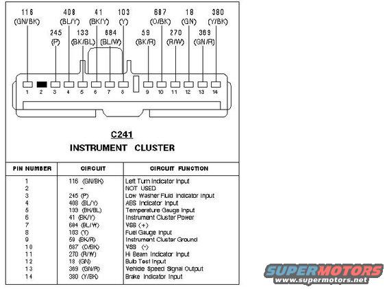
Wiring diagram of the C241 instrument cluster connector listing each pin's circuit, wire color code, and function.
This document is a connector pinout reference for connector C241, the instrument cluster connector, showing a 14-pin connector face drawing with each cavity's circuit number and wire color labeled, followed by a table listing pin number, circuit number/wire color, and circuit function. Functions covered include the left turn indicator input (pin 1, circuit 116 GN/BK), low washer fluid indicator (pin 3, 245 P), ABS indicator (pin 4, 408 BL/Y), temperature gauge input (pin 5, 133 BK/BL), instrument cluster power (pin 6, 41 BK/Y), vehicle speed sensor VSS+ and VSS- (pins 7 and 10, circuits 684 BL/W and 687 O/BK), fuel gauge input (pin 8, 103 Y), cluster ground (pin 9, 59 BK/R), high beam indicator (pin 11, 270 R/W), bulb test input (pin 12, 18 GN), vehicle speed signal output (pin 13, 369 GN/R), and brake indicator input (pin 14, 380 Y/BK). Pin 2 is marked NOT USED. A reader can identify which wire and color corresponds to each cluster function, useful for gauge cluster swaps, VSS diagnosis, and troubleshooting warning indicators. The upload filename indicates it applies to a 1994 Ford Probe cluster, though the document itself shows no year.
Is this accurate? Sign in to help verify it.
Frequently asked questions
- What connector is C241 on the Ford Probe?
- C241 is the instrument cluster connector, a 14-pin connector whose pinout and circuit functions are shown in this document.
- Which pins on C241 are the vehicle speed sensor (VSS) wires?
- Pin 7 is VSS (+) on circuit 684 (BL/W) and pin 10 is VSS (-) on circuit 687 (O/BK). Pin 13, circuit 369 (GN/R), is the Vehicle Speed Signal Output.
- What wire provides power and ground to the instrument cluster?
- Pin 6, circuit 41 (BK/Y), is Instrument Cluster Power, and pin 9, circuit 59 (BK/R), is Instrument Cluster Ground.
- Which pin is the fuel gauge input on connector C241?
- Pin 8, circuit 103 with a yellow (Y) wire, is the Fuel Gauge Input.
- Are any pins on C241 unused?
- Yes, pin 2 is marked NOT USED.
Comments
More from this build






No comments yet.