1990 Ford Bronco Manual A/C-Heater Wiring Diagram 54-2 - Blower & AC Clutch
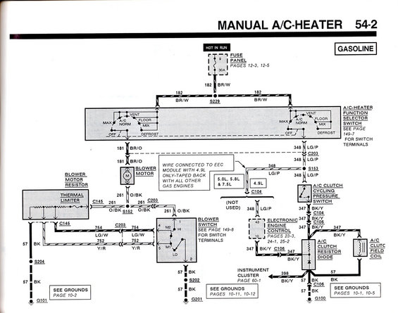
Manual A/C-heater electrical schematic for 1995 Ford Bronco gasoline trucks: blower motor resistor, thermal limiter, function selector switch and A/C clutch cycling pressure switch circuits with wire colors.
This document is page 54-2 of a Ford factory wiring diagram set, covering the Manual A/C-Heater system for gasoline-engine vehicles. It shows power originating from fuse 9 (30A, hot in run) in the fuse panel (pages 12-3, 12-5), feeding via circuit 182 BR/W through splice S229 to the A/C-heater function selector switch (positions OFF, MAX, A/C NORM, VENT, FLOOR, MIX, DEFROST; switch terminals on page 149-7). One branch (181 BR/O) feeds the blower motor, then through circuit 261 O/BK to the blower motor resistor with thermal limiter and the blower switch (terminals on page 149-8), using circuits 754 LG/W and 752 Y/R, grounding via circuit 57 BK at G101 and G201. The other branch (348 LG/P) feeds the A/C clutch cycling pressure switch and, on 4.9L engines only, connects to the electronic engine control (EEC) module at pins 43 and 10 (taped back on 5.0L, 5.8L and 7.5L engines). Circuit 347 BK/Y runs through connectors C104 and C106 to the A/C clutch resistor diode and A/C clutch field coil, with circuit 398 BK/Y to the instrument cluster (page 60-1) and grounds at G100. Splices S152, S153, S202, S204 and connectors C145, C203 are identified.
Is this accurate? Sign in to help verify it.
Frequently asked questions
- What fuse powers the manual A/C-heater system?
- Fuse 9, a 30A fuse in the fuse panel that is hot in run, feeding circuit 182 BR/W (fuse panel details on pages 12-3 and 12-5).
- What wire color feeds the blower motor?
- Circuit 181 BR/O (brown/orange) feeds the blower motor from the A/C-heater function selector switch; circuit 261 O/BK runs from the blower motor to the resistor and blower switch.
- Which engines have the A/C wire connected to the EEC module?
- The 348 LG/P wire is connected to the EEC module only with the 4.9L engine; it is taped back with all other gas engines (5.0L, 5.8L & 7.5L, where connector C104 is not used).
- What circuit runs from the A/C clutch cycling pressure switch to the clutch?
- Circuit 347 BK/Y (black/yellow) runs from the A/C clutch cycling pressure switch through connectors C104 and C106 to the A/C clutch resistor diode and A/C clutch field coil.
- What positions does the A/C-heater function selector switch have?
- OFF, MAX, A/C NORM, VENT, FLOOR, MIX, and DEFROST. Switch terminal details are on page 149-7.
Comments
More from this build













No comments yet.