1988-93 Ford Mustang Mass Air EEC-IV Wiring Diagram - Sensor & Injector Pinout
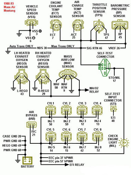
1988-93 Mass Air Mustang EEC-IV engine wiring diagram mapping sensors (ECT, ACT, TPS, BP, VSS, MAF, HEGO) and 8 injectors to EEC pin numbers and grounds.
This is a color-coded EEC-IV wiring/pinout schematic for 1988-1993 Mass Air Ford Mustang electronic fuel injection systems. It maps each engine management sensor and actuator connector to its EEC computer pin number. Sensors shown include the Vehicle Speed Sensor (VSS, pins 3 and 6), Engine Coolant Temp sensor (ECT, pin 7), Air Charge Temp sensor (ACT, pin 25), Throttle Position Sensor (TPS, pin 47), Barometric Pressure sensor (BP, pin 45), left and right Heated Exhaust Gas Oxygen sensors (L-HEGO pin 43, R-HEGO pin 29), and the Mass Airflow sensor (MAF pin 50, MAF RTN pin 9), which also feeds the MA/O2 relay. Shared reference wiring includes SIG RTN (pin 46), VREF (pin 26), and NDS (pin 30, with a note distinguishing automatic vs. manual transmission wiring). Diagnostic connections include the Self-Test Connector (STO/MIL pin 17), Self-Test Input connector (STI pin 48), and the Check Engine Light (MIL). All eight fuel injectors are mapped by cylinder: INJ 1-8 at pins 58, 59, 12, 13, 14, 15, 42, and 52. The Idle Air Bypass (IAB/ISC) uses pin 21. Grounds shown are CASE GND 20, PWR GND 40, HEGO GND 49, and PWR GND 60, with battery power via VPWR at EEC pins 37 and 57 through the EFI relay.
Is this accurate? Sign in to help verify it.
Frequently asked questions
- What EEC pins do the fuel injectors use on a 1988-93 Mass Air Mustang?
- INJ 1 = pin 58, INJ 2 = pin 59, INJ 3 = pin 12, INJ 4 = pin 13, INJ 5 = pin 14, INJ 6 = pin 15, INJ 7 = pin 42, INJ 8 = pin 52.
- Which EEC pins does the MAF sensor connect to?
- The Mass Airflow (MAF) sensor connects to EEC pin 50 (MAF signal) and pin 9 (MAF RTN); its circuit also connects to the MA/O2 relay.
- What pins are the HEGO oxygen sensors on?
- The LH heated exhaust oxygen sensor (L-HEGO) is pin 43 and the RH sensor (R-HEGO) is pin 29, with HEGO GND on pin 49.
- Which EEC pins receive battery power (VPWR)?
- EEC pins 37 and 57 receive VPWR through the EFI relay from the battery.
- What pin is the Throttle Position Sensor (TPS) signal?
- TPS signal is EEC pin 47, with VREF on pin 26 and SIG RTN on pin 46.
Comments
More from this build













No comments yet.