1995 Ford Bronco A/C Heater Wiring Diagram - Clutch Cycling Switch Circuit 54-3

Reference · 1987-1991 BroncoAll 175 wiring diagrams
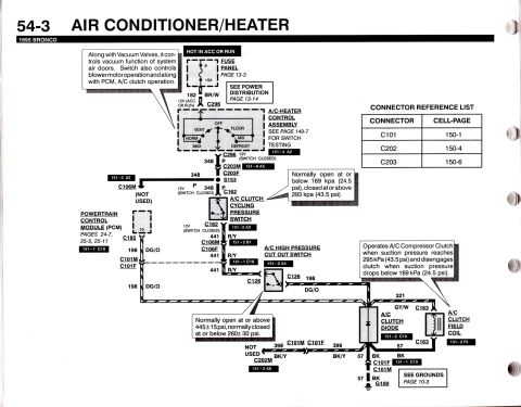













A/C-heater schematic for 1995 Ford Bronco: PCM-controlled A/C clutch, cycling pressure switch and high-pressure cut-out switch with kPa/psi thresholds and connector reference list.
Part of 1987-1991 Ford Bronco Wiring Diagrams
This is page 54-3 of the 1995 Ford Bronco electrical/vacuum troubleshooting manual, showing the wiring diagram for the Air Conditioner/Heater A/C clutch control circuit. Power originates from fuse 6 (15A) in the fuse panel (hot in ACC or RUN) via circuit 182 BR/W to the A/C-heater control assembly (positions OFF, VENT, FLOOR, NORM, MIX, MAX, DEFROST). From the switch, circuit 348 P feeds through connectors C296, C203M/C203F, and splice S153 to the A/C clutch cycling pressure switch (C162), which is normally open at or below 169 kPa (24.5 psi) and closed at or above 293 kPa (43.5 psi). Circuit 441 R/Y then runs through the A/C high pressure cut out switch (C126), normally open at or above 445±15 psi and closed at or below 260±30 psi. Circuit 321 GY/W and 198 DG/O connect to the A/C clutch diode and A/C clutch field coil (C163), with grounds via circuit 57 BK to G100. The Powertrain Control Module (PCM) connects via circuit 198 DG/O at C185 pin 10. A connector reference list gives cell-pages for C101 (150-1), C202 (150-4), and C203 (150-6), with cross-references to power distribution (page 13-14), grounds (page 10-3), and switch testing (page 149-7).
This document covers 1995, which may differ from this 1990 Ford Bronco.
Is this accurate? Sign in to help verify it.
Frequently asked questions
- What fuse powers the A/C-heater control circuit on a 1995 Bronco?
- Fuse 6, a 15A fuse in the fuse panel, hot in ACC or RUN, feeding circuit 182 BR/W (see Power Distribution, page 13-14; fuse panel on page 13-3).
- At what pressures does the A/C clutch cycling pressure switch operate?
- It is normally open at or below 169 kPa (24.5 psi) and closed at or above 293 kPa (43.5 psi).
- What are the operating pressures of the A/C high pressure cut out switch?
- It is normally open at or above 445±15 psi and normally closed at or below 260±30 psi.
- What wire colors are used in the 1995 Bronco A/C clutch circuit?
- Circuit 182 BR/W (brown/white), 348 P (purple), 441 R/Y (red/yellow), 198 DG/O (dark green/orange), 321 GY/W (gray/white), 398 BK/Y (black/yellow), and 57 BK (black) to ground G100.
- Where can connector face views for this circuit be found?
- Per the Connector Reference List: C101 at cell-page 150-1, C202 at 150-4, and C203 at 150-6.






No comments yet.