1996 Ford Probe Instrument Cluster Wiring Diagram - Tach, Oil Gauge, Alternator

Reference · 1993-1997 ProbeAll 65 wiring diagrams
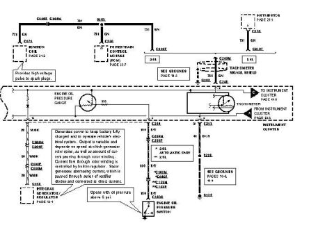
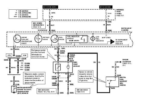
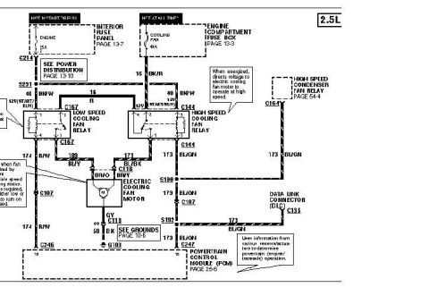
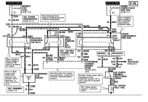
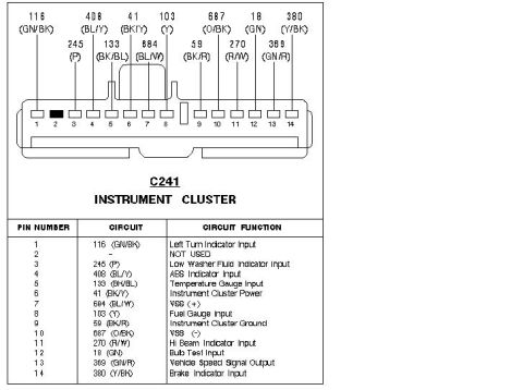









Wiring diagram of the tachometer and engine oil pressure gauge circuits with color-coded wires and connectors.
Part of 1993-1997 Ford Probe Wiring Diagrams
This scanned wiring diagram covers the instrument cluster circuits for a Ford Probe, specifically the tachometer, engine oil pressure gauge, ignition coil, distributor, powertrain control module (PCM), and integral generator/regulator (alternator) circuits. It shows the 731 GN and 751 GN tachometer signal wires running from the ignition coil (page 21-2), PCM (page 13-7), and distributor (page 21-3) through connectors C171, C246, C170, C210F, C249F and C249M (with a tachometer signal shield) into the instrument cluster tachometer. Applications are split between 2.0L and 2.5L engines, with connector variations noted for 2.0L automatic only (C168M/C151F) versus 2.5L (C151M/C167F). The oil pressure gauge circuit runs on a P/Y and P/V wire through C249, C1000 and the engine oil pressure switch (which opens with oil pressure above 6 psi) to ground G105. The charging circuit uses 20 W/BK wires through C206M/C206F and C149F/C146M to the integral generator/regulator (page 12-1), with an explanatory note describing how the alternator's built-in regulator controls rotor winding current and rectifies stator AC output to DC. Ground references include G208 (page 10-8) and grounds on pages 10-4/10-5.
Is this accurate? Sign in to help verify it.
Frequently asked questions
- At what pressure does the engine oil pressure switch open?
- The diagram states the oil pressure switch "opens with oil pressure above 6 psi."
- What wire color carries the tachometer signal from the ignition coil and distributor?
- Circuit 731 GN (green) carries the tachometer signal, with 751 GN running to the ignition coil and PCM; the tachometer line uses a tachometer signal shield near connector C249M.
- Which connectors differ between the 2.0L automatic and the 2.5L engine?
- The diagram marks C168M and C151F as "2.0L AUTOMATIC ONLY" (*) and C151M and C167F as 2.5L (**).
- How does the integral generator/regulator work according to this diagram?
- It keeps the battery charged and powers the vehicle's electrical system; output varies with rotor speed and rotor winding current, which is controlled by the built-in regulator. The stator's alternating current is passed through rectifier diodes and converted to direct current.
- What wire colors feed the oil pressure gauge circuit?
- Circuit 110 P/Y at connector C249 and 110 P/V down through C1000 to the engine oil pressure switch, which grounds at G105.






No comments yet.