1993 Ford Probe PCM Connector Pinouts C247 C248 C249 - Wiring Diagram
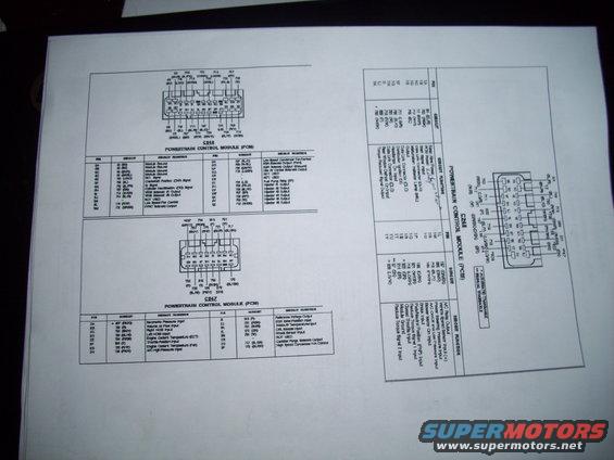
Photographed PCM connector pinout charts listing each pin's circuit and function for multiple connectors.
This document is a scanned page of Ford Powertrain Control Module (PCM) connector pinout diagrams and tables covering three PCM connectors: C248, C247, and C249. For each connector, a physical connector face drawing is shown with wire circuit numbers and color codes called out for each cavity, followed by a table listing every pin (e.g., 3A–3Z, 2A–2P, 1A–1U), its circuit number, wire color abbreviation, and circuit function. Functions documented include module grounds, crankshaft position (CKP), G, and cylinder identification (CID) signals, VRIS solenoid outputs, fuel pump relay, injectors #1–#6, EGR solenoid vent/vacuum outputs, idle air control, HO2S (left/right) inputs, volume air flow, engine coolant temperature, throttle position, knock sensor, A/C high pressure input, canister purge solenoid, condenser fan controls (low and high speed), data link connector (DLC), MIL output, vehicle speed sensor, park/neutral position input, and torque-reduction signals. Footnotes distinguish circuits that apply only to automatic transaxle (*) versus manual transaxle (**) vehicles. A reader can use this page to identify PCM pin assignments, circuit numbers, and wire colors when diagnosing engine management, injector, sensor, or transaxle-related electrical problems. The V6-style content (six injectors, VRIS solenoids) is consistent with a Probe-family PCM harness reference.
Is this accurate? Sign in to help verify it.
Frequently asked questions
- Which PCM pins control the fuel injectors on this connector diagram?
- On connector C248, pins 3U through 3Z carry injector outputs: 3U circuit 705 (Injector #1), 3V 706 (Injector #2), 3W 707 (Injector #3), 3X 708 (Injector #4), 3Y 709 (Injector #5), and 3Z 710 (Injector #6).
- Which pin is the fuel pump relay circuit?
- Pin 3T on connector C248, circuit 704 (LG), is listed as the Fuel Pump Relay (FP) circuit.
- Where are the oxygen sensor inputs on the PCM?
- On connector C247, pin 2C circuit 720 (BK/Y) is the Right HO2S Input and pin 2D circuit 785 (BL/W) is the Left HO2S Input.
- What do the asterisk footnotes on the C249 table mean?
- A single asterisk (*) marks circuits used with the automatic transaxle, and a double asterisk (**) marks circuits used with the manual transaxle.
- Which connector carries the Keep Alive Power and PCM Power circuits?
- Connector C249: pin 1A circuit 84 (BL/R) is Keep Alive Power and pin 1B is PCM Power.
Comments
More from this build







No comments yet.