Ford Probe PCM Connector Pinouts C248, C246, C247 - Wiring Diagram & Pin Table
Reference · 1993-1997 ProbeAll 65 wiring diagrams

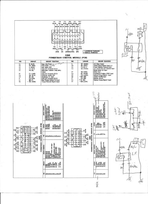
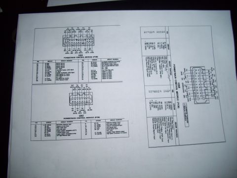
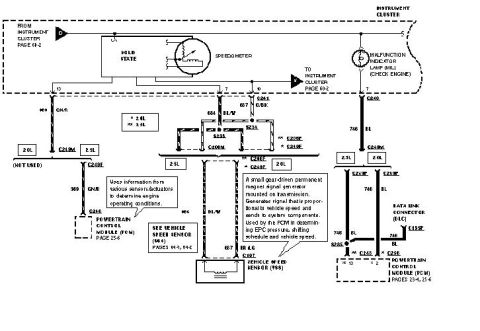
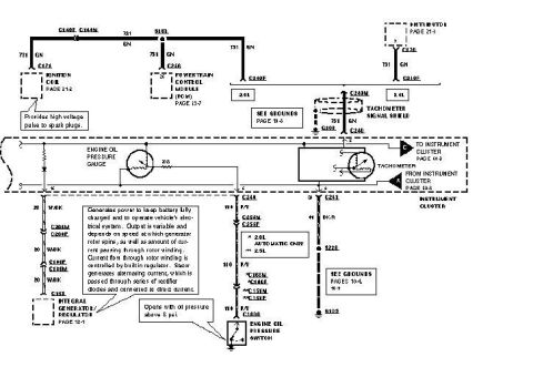
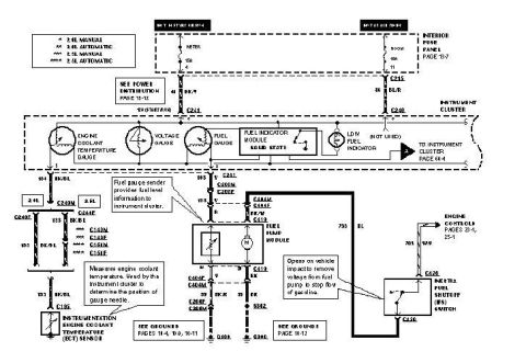









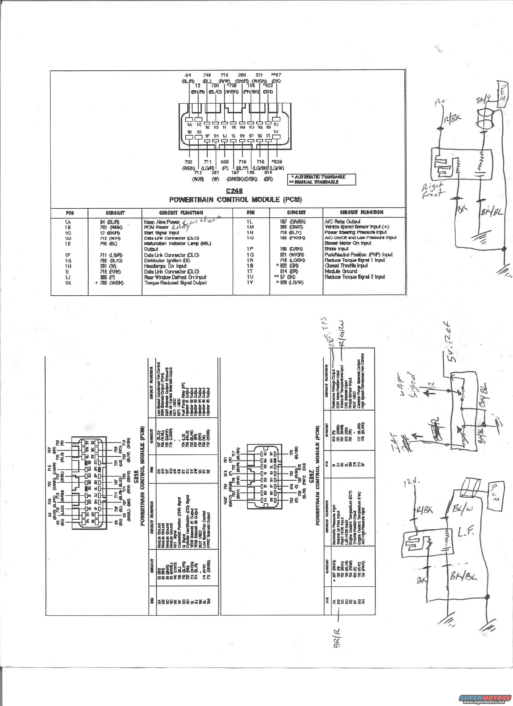
Powertrain control module connector pinout charts with handwritten wiring annotations and sketched circuits.
Part of 1993-1997 Ford Probe Wiring Diagrams
This scanned page presents Ford Powertrain Control Module (PCM) connector pinout diagrams and tables, apparently from a Ford Probe wiring/EVTM manual. The main, clearly legible section covers connector C248, showing the PCM connector face with circuit numbers and wire colors, plus a complete pin table (pins 1A-1V) listing circuit numbers, wire colors, and functions such as Keep Alive Power (94 BL/R), PCM Power (702 R/BK), Start Signal Input, Data Link Connector pins, MIL output, Distributor Ignition, A/C Relay Output, Vehicle Speed Sensor Input, Power Steering Pressure Input, Brake Input, Park/Neutral Position Input, Reduce Torque signals, Closed Throttle Input, and Module Ground. Footnotes distinguish automatic (*) versus manual (**) transaxle circuits. Two additional rotated tables cover connectors C246 (module grounds, CKP/G/CID signals, VRIS solenoids, fan controls, EGR solenoids, IAC, fuel pump relay, injectors 1-6) and C247 (barometric pressure, VAF, HO2S inputs, ECT, TPS, reference voltage, EGR position, IAT, knock sensor, canister purge, condenser fan control). Handwritten notes annotate reference voltage/TPS, VAF signal, IAT, and sketch left-front and right-front sensor/relay circuits with wire colors (R/BK, BK, BK/BL). Useful for diagnosing PCM wiring, sensor circuits, and pin functions.
Is this accurate? Sign in to help verify it.
Frequently asked questions
- What is pin 1A on the Ford Probe PCM connector C248?
- Pin 1A is circuit 94 (BL/R), Keep Alive Power (annotated 'Constant' by the uploader).
- Which C248 PCM pins are used for the Data Link Connector (DLC)?
- Pins 1D (712 W/R), 1F (711 LG/R), and 1I (715 R/W) are all Data Link Connector (DLC) circuits.
- What do the asterisks mean in the C248 pin table?
- A single asterisk (*) indicates the circuit applies to automatic transaxle vehicles; a double asterisk (**) indicates manual transaxle.
- Which pin is the PCM module ground on connector C248?
- Pin 1T, circuit 914 (BR), is Module Ground.
- What C248 pin carries the vehicle speed sensor signal?
- Pin 1M, circuit 369 (GN/R), is the Vehicle Speed Sensor Input (+).






No comments yet.