2000 Mazda 626 ES 2.5L Engine Performance Wiring Diagram - PCM Pinout (1 of 3)

Reference · 1993-1997 ProbeAll 65 wiring diagrams

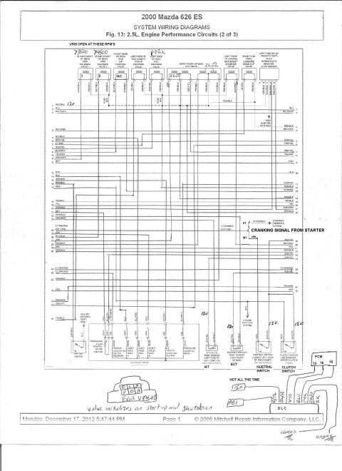
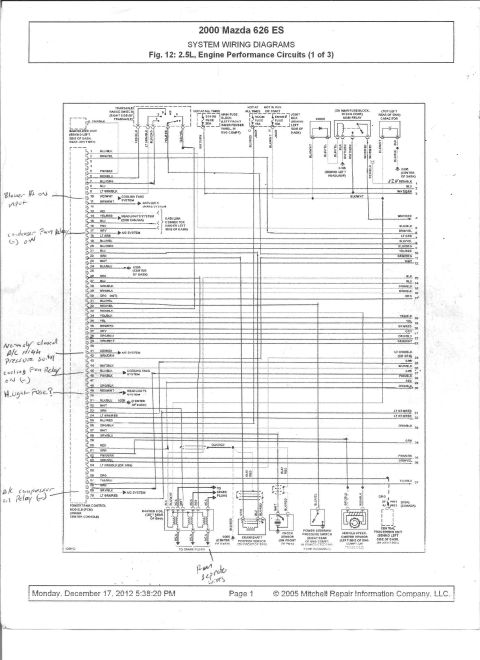
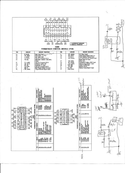
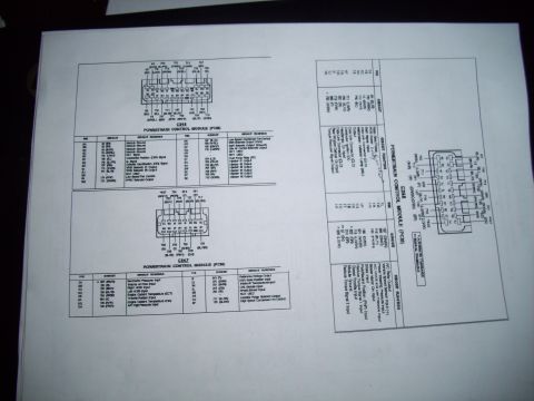
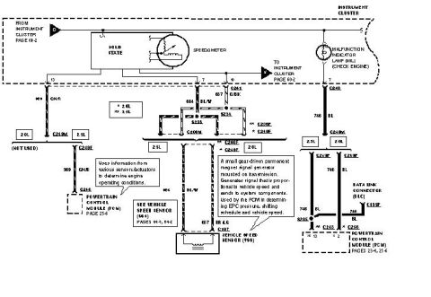
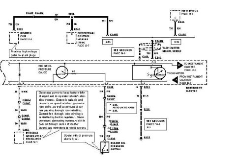
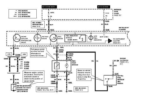









2000 Mazda 626 ES 2.5L engine performance circuits system wiring diagram (Mitchell, Fig 12 of 3) with handwritten notes on fuel pump and A/C relay coils and pressure switch.
Part of 1993-1997 Ford Probe Wiring Diagrams
This document is page 1 of a three-page Mitchell Repair Information system wiring diagram set titled "2000 Mazda 626 ES, SYSTEM WIRING DIAGRAMS, Fig. 12: 2.5L, Engine Performance Circuits (1 of 3)." It shows the Powertrain Control Module (PCM, located under the center console) with a full 70-pin left connector pinout listing wire colors (e.g., pin 1 BLU/BLK, pin 5 PNK/BLK, pin 41 VIO/RED to the A/C system) plus a 37-line right-side connector list. Connected circuits include the transaxle range switch, immobilizer unit, main fuse block (EGI INJ 30A fuse), joint box (ROOM 15A and ENGINE 10A fuses), main relay, diode, capacitor, ignition coil with spark plug leads, crankshaft position sensor, knock sensor, power steering pressure switch, vehicle speedometer sensor, and the central processing unit behind the left side of the dash. Grounds G106 (behind left headlamp) and G205 (center of dash) are identified. Handwritten annotations by the owner label several PCM pins: blower Hi input, condenser fan relay (-), normally closed A/C high pressure switch, cooling fan relay (-), headlight fuse, and A/C compressor relay (-). The page is dated with a 2012 print stamp and 2005 Mitchell copyright.
Is this accurate? Sign in to help verify it.
Frequently asked questions
- Where is the PCM located on a 2000 Mazda 626 ES?
- The diagram labels the Powertrain Control Module (PCM) as being located under the center console.
- What fuses power the engine performance circuits on the 2000 Mazda 626 2.5L?
- The EGI INJ 30A fuse in the main fuse block (left front inner fender panel, engine compartment, hot at all times), the ROOM 15A fuse (hot at all times, JB-07) and the ENGINE 10A fuse (hot in run or start, JB-08) in the joint box behind the left side of the dash.
- Which PCM pins control the cooling fans and A/C on this diagram?
- Pin 10 (VIO/WHT) and pin 45 (BLU/BLK) go to the cooling fans system; pin 17 (GRY), pin 41 (VIO/RED) and pin 69 (GRY/BLK) go to the A/C system. Handwritten notes identify pin 45 as cooling fan relay (-), pin 17 as condenser fan relay (-), pin 41 as the normally closed A/C high pressure switch, and pin 69 as A/C compressor relay (-).
- Where are the ground points G106 and G205 located?
- G106 is behind the left headlamp and G205 is at the center of the dash.
- Where is the crankshaft position sensor and what are its wire colors?
- The crankshaft position sensor is on the front of the engine, with GRN, BLU and BLK/RED wiring shown, plus a BLU/RED connection running to the PCM area.






No comments yet.