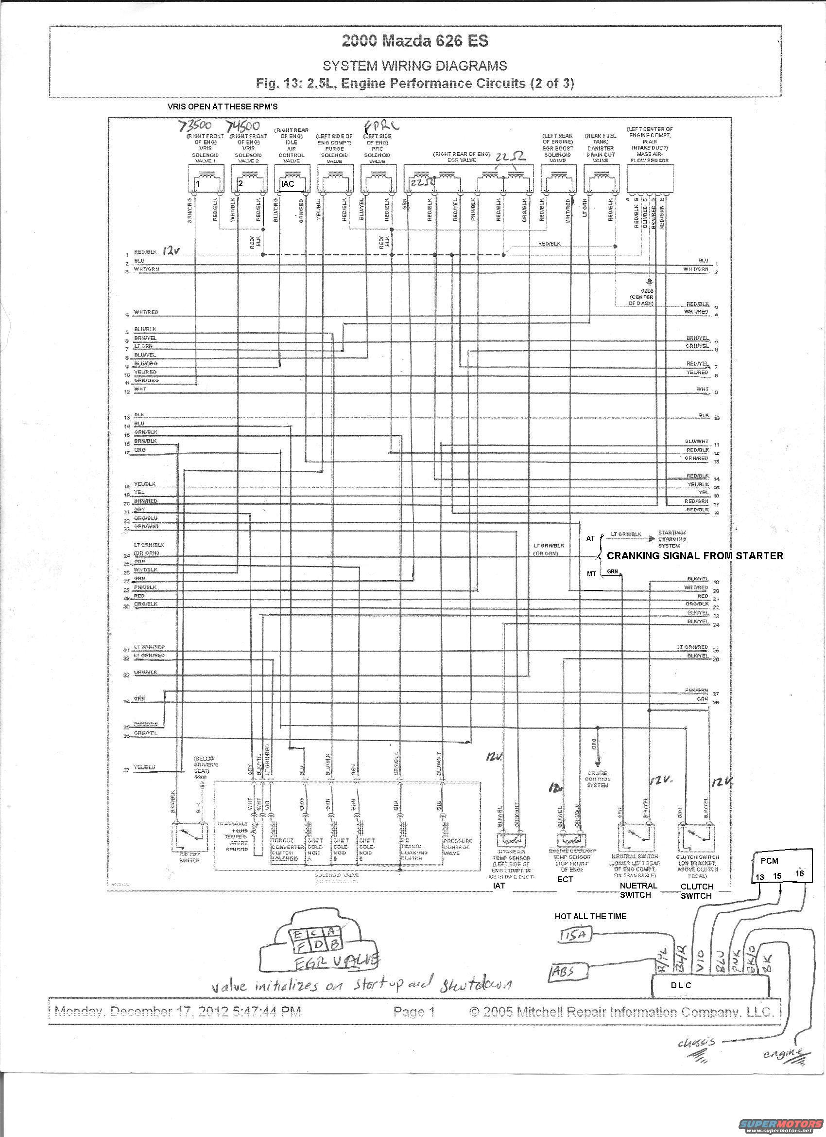
2000 Mazda 626 ES 2.5L Engine Performance Wiring Diagram (2 of 3) - PCM & EGR
Reference · 1993-1997 ProbeAll 65 wiring diagrams

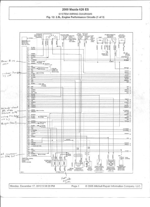
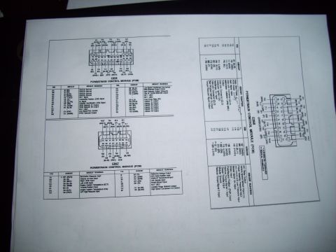
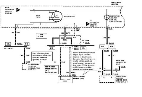
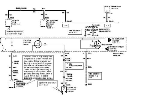
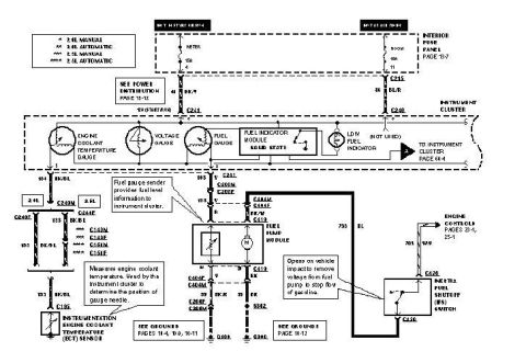









Mazda 626 ES 2.5L engine performance circuits system wiring diagram with labeled components and connectors.
Part of 1993-1997 Ford Probe Wiring Diagrams
This document is page 2 of a three-page Mitchell Repair Information system wiring diagram set (Fig. 13) covering the engine performance circuits for a 2000 Mazda 626 ES with the 2.5L V6 engine. It shows PCM pinouts (numbered pins with wire colors on both left and right sides of the diagram) connecting to numerous engine management components: VRIS solenoid valves 1 and 2, idle air control (IAC) valve, purge solenoid valve, PRC solenoid valve, EGR valve, EGR boost solenoid valve, canister drain cut valve, and the mass air-flow sensor (pins A-E). Lower sections cover the transaxle solenoid valve assembly (torque converter clutch solenoid, shift solenoids A/B/C, 3-2 timing/coasting clutch, pressure control valve), transaxle fluid temperature sensor, intake air temp (IAT) sensor, engine coolant temp (ECT) sensor, neutral switch, and clutch switch, with physical locations noted for each component. Extensive handwritten annotations add VRIS opening RPMs (~3500 and ~4500), 12V test-point markings, an EGR valve connector pinout (E-C-A/F-D-B) with the note "valve initializes on startup and shutdown," a PCM connector sketch (pins 13, 15, 16), a DLC connector with wire colors, fuse notes ("HOT ALL THE TIME"), and a "cranking signal from starter" callout distinguishing AT (LT GRN/BLK) and MT (GRN) wiring.
This document covers 2000, which may differ from this 1993 Ford Probe.
Is this accurate? Sign in to help verify it.
Frequently asked questions
- What wire color carries the cranking signal from the starter on the 2000 Mazda 626 2.5L?
- Per the diagram, on automatic transmission (AT) models it is LT GRN/BLK (or GRN) going to the starting/charging system, while manual transmission (MT) models use a GRN wire. A typed annotation labels this "CRANKING SIGNAL FROM STARTER."
- Where are the VRIS solenoid valves located and when do they open?
- Both VRIS solenoid valve 1 and valve 2 are located at the right front of the engine. Handwritten notes indicate VRIS opens at approximately 3500 RPM (valve 1) and 4500 RPM (valve 2).
- Where is the engine coolant temperature (ECT) sensor on this engine?
- The diagram places the engine coolant temp sensor at the top front of the engine, wired with a BLU/YEL wire; a handwritten note marks 12V at the connector.
- What is the EGR valve connector pinout shown in the handwritten notes?
- A hand-drawn sketch shows the EGR valve connector pins arranged as E-C-A over F-D-B, with a note that the valve initializes on startup and shutdown.
- Where is the mass air-flow sensor located and how many pins does it have?
- The mass air-flow sensor is at the left center of the engine compartment, in the air intake duct, and the diagram shows a 5-pin connector labeled A, B, C, D, and E.






No comments yet.