Home/
Registry/
Ford/
Bronco/
1978-1979/
“buyers guide”/
Photo
supermotors.net/registry/media/975550
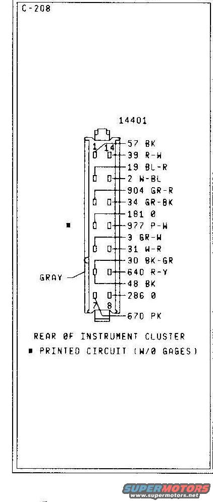
Ford Bronco Instrument Cluster Connector C-208 Pinout (W/O Gauges) 14401
Reference · 1978-1979 BroncoAll 116 wiring diagrams
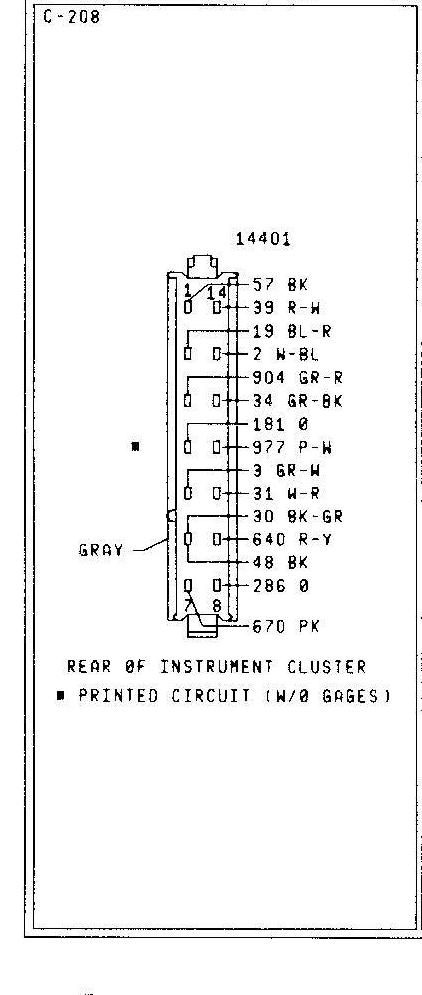


Wiring connector diagram for rear of instrument cluster printed circuit (C-208) without gages, listing pin wire numbers and colors.
Part of 1978-1979 Ford Bronco Wiring Diagrams
This document is a connector pinout diagram labeled C-208 for the rear of a Ford instrument cluster printed circuit in the without-gauges (W/O GAGES) configuration. The connector is identified by base part number 14401 and is noted as GRAY in color. The diagram shows a 14-plus-pin connector viewed from the rear of the instrument cluster, with pin positions numbered 1 through 14 across the top row and 7 and 8 marked at the bottom, plus an additional terminal for circuit 670. Each terminal is labeled with its circuit number and wire color code: 57 BK, 39 R-W, 19 BL-R, 2 W-BL, 904 GR-R, 34 GR-BK, 181 O, 977 P-W, 3 GR-W, 31 W-R, 30 BK-GR, 640 R-Y, 48 BK, 286 O, and 670 PK. A filled square symbol marks a specific pin position referenced in the legend as pertaining to the printed circuit without gauges. This diagram lets a reader identify each wire entering the instrument cluster connector by circuit number and insulation color, useful for diagnosing warning-light and cluster wiring on a classic Ford Bronco or similar truck.
Is this accurate? Sign in to help verify it.
Frequently asked questions
- What connector does this diagram show?
- Connector C-208, the connector at the rear of the instrument cluster printed circuit for clusters without gauges (W/O GAGES), part number reference 14401.
- What color is the instrument cluster connector C-208?
- The connector is labeled GRAY in the diagram.
- What wire circuits connect to the instrument cluster connector?
- Circuits 57 BK, 39 R-W, 19 BL-R, 2 W-BL, 904 GR-R, 34 GR-BK, 181 O, 977 P-W, 3 GR-W, 31 W-R, 30 BK-GR, 640 R-Y, 48 BK, 286 O, and 670 PK.
- How are the pins numbered on this connector?
- Pin positions 1 and 14 are marked at the top of the connector and pins 7 and 8 at the bottom, indicating a 14-position layout.
- What does the square symbol mean in this diagram?
- The filled square marks a pin location and the legend states it refers to the PRINTED CIRCUIT (W/O GAGES) version of the cluster.






No comments yet.