Home/
Registry/
Ford/
Bronco/
1978-1979/
“buyers guide”/
Photo
supermotors.net/registry/media/975552
Ford Bronco Turn Signal Switch Connector C-305 Pinout & Wire Colors (9A840)

Reference · 1978-1979 BroncoAll 116 wiring diagrams
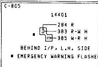
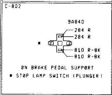
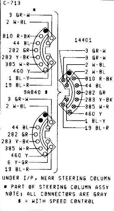
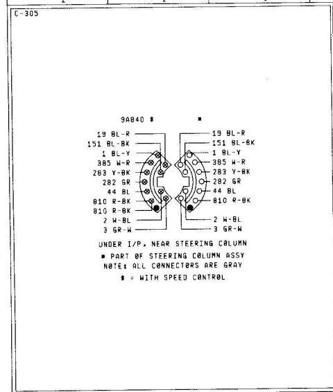
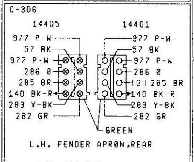
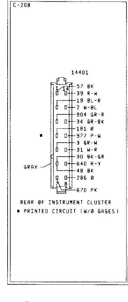
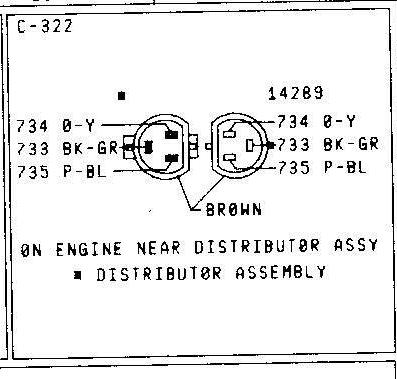
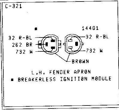
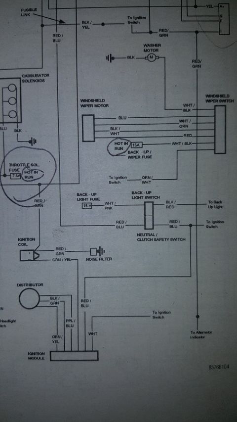
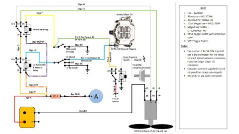
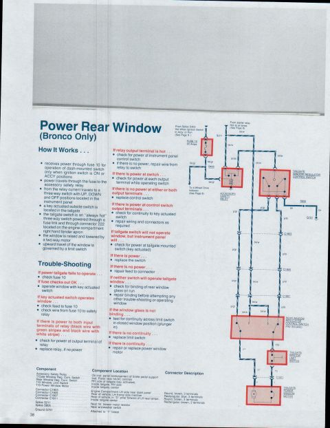
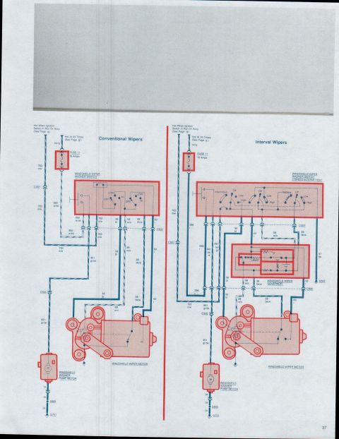
Wiring connector diagram for steering column assembly (C-305) under I/P, listing all-gray connector pin wire numbers and colors.
Part of 1978-1979 Ford Bronco Wiring Diagrams
This document is a wiring/connector pinout diagram labeled C-305 showing the mating halves of a turn signal switch connector (Ford base part number 9A840, footnoted as applicable with speed control). Two semicircular connector faces are shown side by side, one being part of the steering column assembly and the other the vehicle harness side, with each pin identified by circuit number and wire color code. The pins on both halves are: 19 BL-R (blue-red), 151 BL-BK (blue-black), 1 BL-Y (blue-yellow), 385 W-R (white-red), 283 Y-BK (yellow-black), 282 GR (green), 44 BL (blue), 810 R-BK (red-black; the column-side half shows 810 R-BK twice), 2 W-BL (white-blue), and 3 GR-W (green-white). Notes state the connector is located under the instrument panel near the steering column, that one half is part of the steering column assembly, that all connectors are gray, and that the asterisk denotes 'with speed control.' A reader can use this to identify, test, or repair the turn signal switch connector wiring by matching circuit numbers and wire colors at each pin position.
Is this accurate? Sign in to help verify it.
Frequently asked questions
- Where is the C-305 turn signal switch connector located?
- According to the diagram, it is located under the I/P (instrument panel), near the steering column.
- What color are the connectors?
- The note on the diagram states that all connectors are gray.
- What wire colors are on the turn signal switch connector?
- The pins are: 19 BL-R, 151 BL-BK, 1 BL-Y, 385 W-R, 283 Y-BK, 282 GR, 44 BL, 810 R-BK, 2 W-BL, and 3 GR-W (the column-side half shows 810 R-BK on two pins).
- What does the asterisk (*) symbol mean on this diagram?
- The legend states * = with speed control; the 9A840 part reference is marked with this symbol.
- Which half of the connector belongs to the steering column?
- The half marked with the solid square symbol is noted as 'part of steering column assy.'
No comments yet.