Home/
Registry/
Ford/
Bronco/
1987-1991/
1988 Ford Bronco/
Photo
supermotors.net/registry/media/1006871
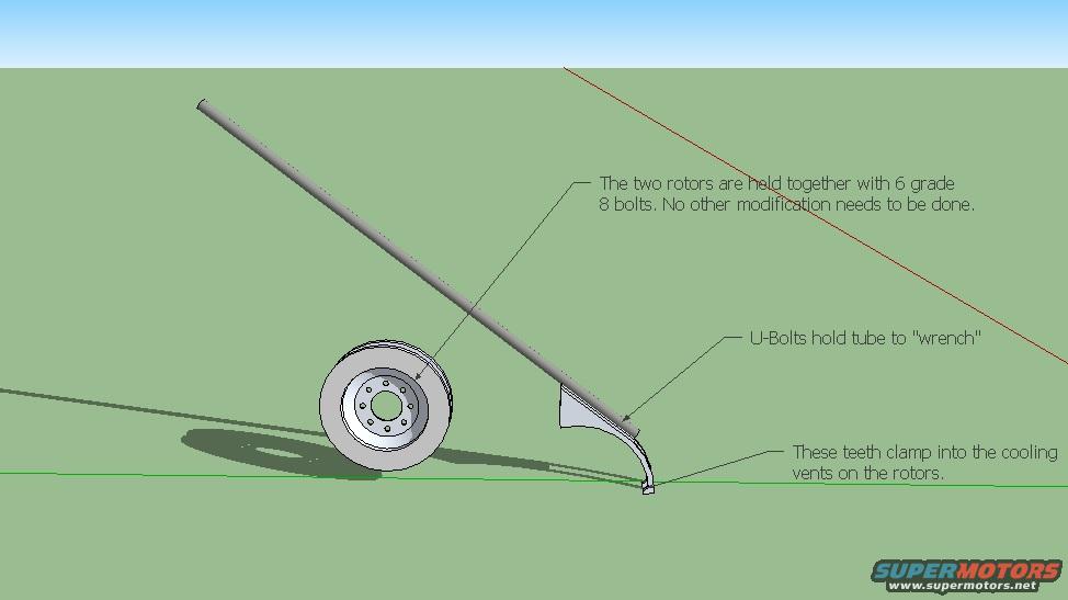
Homemade Brake Rotor Tube Bender Diagram - DIY Bender Design Schematic
Reference · 1987-1991 BroncoAll 110 schematics
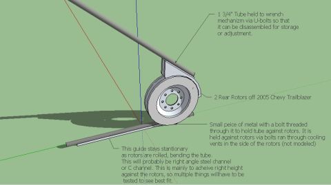













Annotated 3D concept sketch of a tube-bending tool showing two rotors bolted together and a tube clamped with U-bolts.
Part of 1987-1991 Ford Bronco Schematics
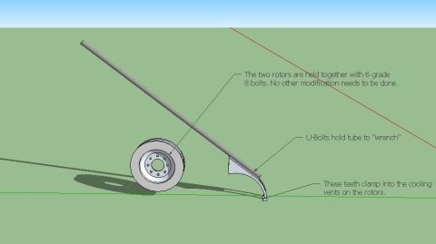
This document is a 3D CAD rendering (appearing to be a SketchUp model) illustrating a homemade tube bender design built from two brake rotors. The drawing shows a long straight tube passing across a pair of stacked brake rotors, with a curved 'wrench' arm engaging the rotor. Three text callouts explain the construction: the two rotors are bolted together with six grade 8 bolts and require no other modification; U-bolts secure the tube to the curved 'wrench' lever arm; and teeth on the end of the wrench clamp into the cooling vents of the rotors to provide leverage. A reader can learn the basic concept of this DIY bender: the stacked rotors act as the bending die/form, the tube is held to a lever arm via U-bolts, and the lever anchors itself in the rotor cooling vents so the tube can be bent around the rotor circumference. The document contains no dimensions, part numbers, vehicle applicability, torque specifications, or year information, it is purely a conceptual schematic with brief annotations. It appears to be one page of a multi-page set (a companion file named 'bender.jpg' exists in the same album).
Is this accurate? Sign in to help verify it.
Frequently asked questions
- How are the two brake rotors held together in this tube bender design?
- The two rotors are held together with 6 grade 8 bolts, and no other modification needs to be done.
- How is the tube attached to the lever arm ('wrench')?
- U-bolts hold the tube to the 'wrench' lever arm.
- How does the wrench arm grip the rotors?
- Teeth on the wrench clamp into the cooling vents on the rotors.
- Do the rotors need to be modified to build this bender?
- No: per the diagram, other than bolting the two rotors together with six grade 8 bolts, no other modification needs to be done.






No comments yet.