Ford 5.0L Secondary Air (Thermactor) System Exploded Parts Diagram - 1990 Bronco

Reference · 1987-1991 BroncoAll 61 exploded parts diagrams
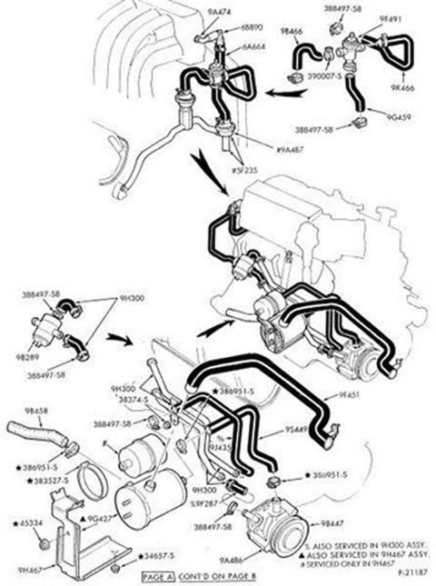
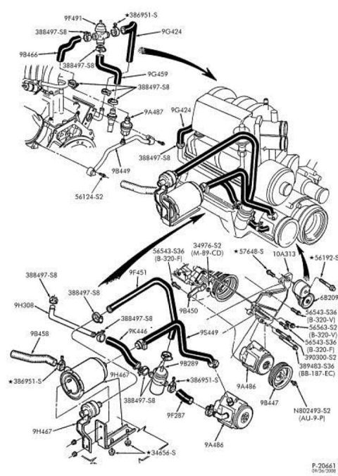








Exploded parts diagram of the thermactor secondary-air plumbing showing hoses, check valves, air pump and Ford part numbers.
Part of 1987-1991 Ford Bronco Exploded Parts Diagrams
This document is an exploded parts diagram of a Ford secondary air injection (Thermactor) system, uploaded to accompany a 1990 Ford Bronco with the 5.0L engine. The line drawing shows an EFI V8 engine assembly with routing of air hoses and tubes, the air pump (9A486), pump pulley (9B447), check valves, bypass/diverter valve components, mounting brackets (9H467), hoses (9B458, 9B466), tubes (9F451, 9F287, 9G424, 9G459, 9D449-series), a bracket/pulley tensioner area (10A313, 6B209), and numerous hose clamps (388497-S8) and fasteners (56543-S36, 56563-S2, 390300-S2, 389483-S36, N802493-S2, 34656-S, 386951-S, 57648-S, 56192-S, 56124-S2, 34976-S2). Each component is identified by its Ford base part number or hardware standard part number, some with suffix codes in parentheses (e.g., B-320-F, M-89-CD, AU-9-P, BB-187-EC). Arrows indicate assembly orientation of hose routings to the engine. The diagram carries the drawing reference P-20661 with a print date of 09/26/2008. A reader can use this figure to identify part numbers for ordering replacement Thermactor/secondary air components, clamps, and mounting hardware, and to see how the air pump, hoses, and tubes route and attach on the engine.
Is this accurate? Sign in to help verify it.
Frequently asked questions
- What is the Ford part number for the secondary air (Thermactor) air pump shown in this diagram?
- The air pump is labeled with base part number 9A486, with its pulley labeled 9B447.
- What part number are the hose clamps used throughout the secondary air system?
- The clamps at multiple hose connections are labeled 388497-S8, and larger clamps are labeled 386951-S (marked with a star).
- What bracket part numbers mount the secondary air components?
- The mounting bracket shown at the lower left is labeled 9H467 (appears twice), attached with fasteners 34656-S.
- What are the part numbers of the main air tubes and hoses in the diagram?
- Tubes and hoses include 9G424, 9G459, 9B449, 9F451, 9K446, 9S449, 9F287, 9B458, 9B466, 9H308, 9B450, and 9B289.
- What fastener hardware numbers are called out for the pump and bracket area?
- Fasteners include 56543-S36 (B-320-F and B-320-V), 56563-S2 (B-320-V), 34976-S2 (M-89-CD), 57648-S, 56124-S2, 390300-S2, 389483-S36 (BB-187-EC), N802493-S2 (AU-9-P), 56192-S, and 34656-S.






No comments yet.