Ford Transmission Range Sensor Wiring Diagram - 60-Pin PCM Pins 30 & 46

Reference · 1992-1996 BroncoAll 95 schematics
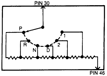
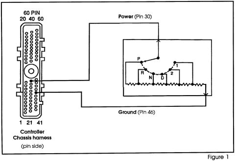



Schematic of a 60-pin controller chassis harness (pin side) wired to a transmission range sensor resistor ladder, with power on Pin 30 and ground on Pin 46.
Part of 1992-1996 Ford Bronco Schematics
This document is a wiring schematic (labeled "Figure 1") showing a transmission range sensor circuit connected to a vehicle controller. On the left is a drawing of a 60-pin controller connector viewed from the pin side of the chassis harness, with corner pins labeled 20, 40, 60 across the top and 1, 21, 41 across the bottom to establish pin numbering orientation. Two wires run from the connector to the sensor: a Power lead identified as Pin 30 and a Ground lead identified as Pin 46. On the right is the internal schematic of a rotary switch/resistive sensor with a wiper contact that moves across positions labeled P, R, N, D, 2, and 1, corresponding to gear-selector positions Park, Reverse, Neutral, Drive, 2, and 1. Each position taps into a chain of series resistors, so the voltage seen at the controller varies depending on the selected gear position. A reader can learn which controller pins carry power and ground for this sensor (Pins 30 and 46 of the 60-pin connector), how the 60-pin connector is numbered when viewed from the pin side, and how the sensor internally uses a resistor ladder to signal gear position. The document contains no wire colors, part numbers, or stated vehicle applicability.
Is this accurate? Sign in to help verify it.
Frequently asked questions
- Which controller pins connect to the transmission range sensor in this diagram?
- Power connects to Pin 30 and Ground connects to Pin 46 of the 60-pin controller connector.
- How is the 60-pin controller connector numbered?
- Viewed from the pin side of the chassis harness, the top corners are pins 20, 40, and 60, and the bottom corners are pins 1, 21, and 41.
- What gear positions does the sensor in this diagram indicate?
- The rotary contact moves through positions labeled P, R, N, D, 2, and 1.
- How does the sensor signal the gear position?
- The diagram shows a wiper contact that taps into a series chain of resistors at each position (P, R, N, D, 2, 1), so the resistance/voltage between the power (Pin 30) and ground (Pin 46) circuits changes with the selected position.






No comments yet.