1995 Ford Bronco Engine Sensor & Connector Location Diagram (5.0L/5.8L)

Reference · 1992-1996 BroncoAll 95 schematics
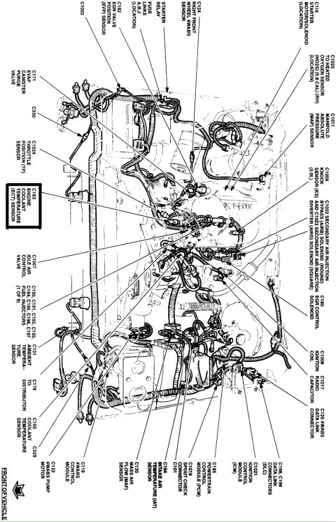

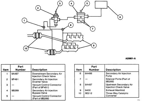
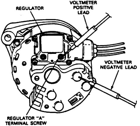
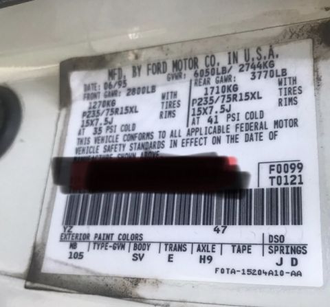
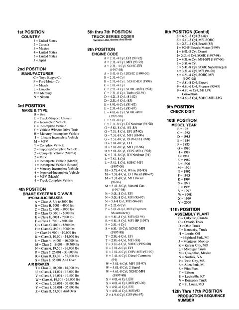




Schematic showing engine wiring harness routing and component/connector locations across the engine bay.
Part of 1992-1996 Ford Bronco Schematics
This document is an engine compartment component location diagram (schematic) for a Ford truck, showing a top view of the engine bay with the wiring harness routing and callout leader lines identifying electrical connectors and components. Each callout gives a connector number (C-number) and the component name. Identified items include the EGR valve position (EVP) sensor (C182), fuse links A, B, J, starter relay, starter motor/solenoid (C116), right front wheel 4WABS sensor (C124), heated oxygen sensor connection (C1025, noted 5.8 CAL RH), MAP sensor (C1011), knock sensor for the 5.0L (C1009), secondary air injection bypass (AIRB, C1022) and diverter (AIRD, C1023) solenoids, EGR control solenoid (C180), ignition coil (C1008), radio capacitor (C1017), 4WABS data link connector (C120), data link connectors C198/C199 (DLC), ignition control module (C1021), powertrain control module (C185), SPOUT check connector (C1019/C101), IAT sensor (C164), MAF sensor (C130), 4WABS control module (C119) and pump motor (C122), coolant temperature sensor (C150), distributor connector (C178), ambient temperature sensor (C131), eight fuel injectors (C190-C197), idle air control valve (C1007), ECT sensor (C183, highlighted), throttle position sensor (C1024), and EVAP canister purge valve (C171). A 'FRONT OF VEHICLE' arrow orients the diagram.
Is this accurate? Sign in to help verify it.
Frequently asked questions
- Where is the engine coolant temperature (ECT) sensor connector on this diagram?
- The ECT sensor is connector C183, highlighted in a box on the diagram, located on the engine near the throttle position (TP) sensor C1024 and idle air control valve C1007.
- What connector number is the mass air flow (MAF) sensor?
- The MAF sensor is connector C130, shown near the intake air temperature (IAT) sensor C164 at the rear/passenger side of the engine bay.
- What are the connector numbers for the fuel injectors?
- The eight fuel injectors use connectors C190, C191, C192, C193, C194, C195, C196, and C197 (1 of 8 shown).
- Where are the secondary air injection solenoids identified?
- C1022 is the secondary air injection bypass (AIRB) solenoid (round) and C1023 is the secondary air injection diverter (AIRD) solenoid (square), shown together on the diagram.
- Which connectors are the data link connectors (DLC)?
- C198 and C199 are the data link connectors (DLC); C120 is the separate 4WABS data link connector.






No comments yet.