1995 Ford Bronco Body Wiring Harness Connector Location Diagram
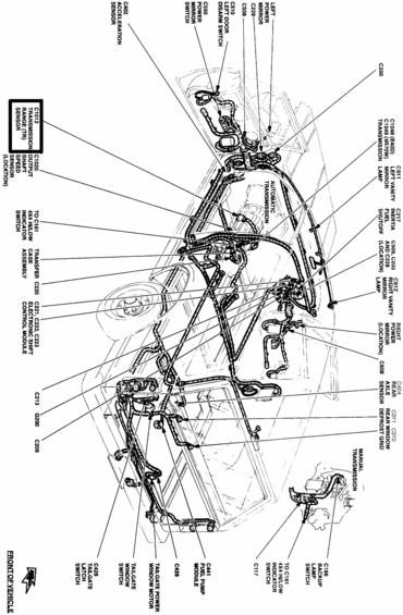
Schematic routing diagram of a vehicle wiring harness with labeled connectors, sensors, and grounds throughout the body.
Part of 1992-1996 Ford Bronco Schematics
This document is a body wiring harness connector location schematic for a Ford Bronco/full-size truck, showing an exploded overhead line drawing of the vehicle body with callout labels identifying electrical connectors, grounds, sensors, and components. Callouts identify connector numbers and the components they serve, including the transmission range (TR) sensor (C1012), output shaft speed sensor (C1020), acceleration sensor (C402), left door disarm switch (C510), power mirror switch (C550), left and right power mirrors (C229, C608), transmission connectors for automatic transmissions C1048 (E4OD) and C1049 (4R70W), left and right vanity mirror lamps (C911, C912), inertia fuel shutoff (C217), rear axle sensor (C404), rear window defrost grid (C310/C311), transfer case assembly (C220), electronic shift control module (C221, C222, C223), tailgate latch switch (C428), tailgate window switch and power window motor, fuel pump module (C441), backup lamp switch (C166), 4x4 hi/low indicator switch (to C161), ground G200, and other connectors (C200, C203, C209, C213, C228, C229, C429, C508, C509, C117). Both automatic and manual transmission variations are shown. An arrow indicates the front of the vehicle. A reader can use this diagram to physically locate wiring connectors and grounds throughout the body of the vehicle.
Is this accurate? Sign in to help verify it.
Frequently asked questions
- Where is the transmission range (TR) sensor connector on this diagram?
- The TR sensor is connector C1012, shown (boxed) at the transmission area along with C1020, the output shaft speed sensor location.
- What are the connector numbers for the E4OD and 4R70W automatic transmissions?
- C1048 is the transmission connector for the E4OD and C1049 is for the 4R70W automatic transmission.
- Which connectors serve the electronic shift control module for the transfer case?
- Connectors C221, C222, and C223 serve the electronic shift control module; the transfer case assembly itself uses connector C220.
- What connector is used for the fuel pump module and inertia fuel shutoff?
- C441 is the fuel pump module connector and C217 is the inertia fuel shutoff connector.
- What tailgate components are identified in this diagram?
- The diagram shows the tailgate latch switch (C428), the tailgate window switch, the tailgate power window motor, and connector C429, along with rear window defrost grid connectors C310 and C311.
Comments
More from this build








No comments yet.