Ford Transmission Range (TR) Sensor Internal Circuit Schematic - Pins 30 & 46

Reference · 1992-1996 BroncoAll 95 schematics
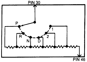
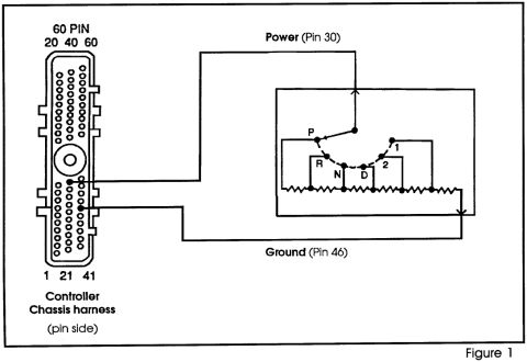




Schematic showing transmission gear-position switch contacts (P, R, N, D, 1, 2) wired between PIN 30 and PIN 46.
Part of 1992-1996 Ford Bronco Schematics
This document is a simple electrical schematic showing an internal circuit of what appears to be a transmission range (TR) sensor, consistent with the upload filename "tr.gif". The diagram shows two external connection points labeled PIN 30 (at top) and PIN 46 (at bottom right). A rotary switch wiper connected to PIN 30 sweeps across six contact positions arranged in an arc, labeled P, R, N, D, 2, and 1, the standard automatic transmission gear selector positions (Park, Reverse, Neutral, Drive, 2, 1). Each of these contact positions taps into a chain of resistors (drawn as a horizontal string of zig-zag resistor symbols along the bottom of the diagram), and the resistor chain terminates at PIN 46. From this diagram a reader can understand that the sensor operates as a variable resistance (voltage divider) network: depending on which gear position the selector is in, a different amount of resistance is placed between PIN 30 and PIN 46, allowing a control module to determine the selected gear from the measured resistance or voltage. The document contains no part numbers, resistance values, wire colors, or year/model applicability statements.
Is this accurate? Sign in to help verify it.
Frequently asked questions
- What pins does this transmission range sensor schematic show?
- The schematic shows two pins: PIN 30, connected to the rotary switch wiper at the top, and PIN 46, connected to the end of the resistor chain at the bottom right.
- What gear selector positions are shown in the diagram?
- Six positions are shown arranged in an arc: P, R, N, D, 2, and 1.
- How does the circuit in this diagram work?
- A wiper connected to PIN 30 contacts one of the six position points (P, R, N, D, 2, 1). Each position taps into a series resistor chain that ends at PIN 46, so each gear position places a different resistance between PIN 30 and PIN 46.
- Does this schematic list resistance values for each gear position?
- No. The diagram shows the resistor network symbolically but does not include any ohm values, part numbers, or wire colors.






No comments yet.