Ford 5.8L V8 Firing Order & Distributor Diagram - 1995 Bronco Cylinder Layout

Reference · 1992-1996 BroncoAll 95 schematics
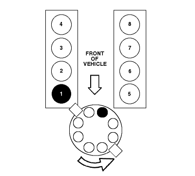

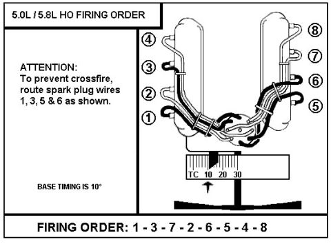



Diagram showing cylinder numbering, firing order and distributor cap terminal positions relative to the front of the vehicle.
Part of 1992-1996 Ford Bronco Schematics
This document is a schematic diagram showing the cylinder numbering layout and distributor orientation for a Ford V8 engine, uploaded as "5.8L firing order" for a 1995 Ford Bronco. The diagram depicts two cylinder banks viewed from above: one bank numbered 4, 3, 2, 1 (front to rear as drawn) and the other numbered 8, 7, 6, 5. Cylinder No. 1 is highlighted in solid black, indicating it is the reference cylinder nearest the front of the vehicle on its bank. A large downward arrow labeled "FRONT OF VEHICLE" establishes the diagram's orientation. Below the cylinder banks, a distributor cap is illustrated with eight terminal posts around a central terminal; the terminal corresponding to cylinder No. 1 is marked in black, and a curved arrow shows the distributor rotor rotating clockwise. From this diagram, a reader can identify which physical cylinder is No. 1, how the remaining cylinders are numbered on each bank, where the No. 1 spark plug wire terminal sits on the distributor cap, and the direction of rotor rotation, information needed to correctly route spark plug wires. Note that the actual firing order sequence (e.g., a list of numbers) is not printed on this diagram; it conveys the layout graphically only.
Is this accurate? Sign in to help verify it.
Frequently asked questions
- Which cylinder is number 1 on this Ford V8 diagram?
- Cylinder No. 1 is the front-most cylinder on the bank numbered 1-2-3-4 (shown filled in black, closest to the front of the vehicle).
- How are the cylinders numbered on each bank?
- One bank is numbered 1, 2, 3, 4 from front to rear, and the other bank is numbered 5, 6, 7, 8 from front to rear.
- Which way does the distributor rotor turn?
- The curved arrow on the diagram shows the distributor rotor rotating clockwise.
- Where is the No. 1 terminal on the distributor cap?
- The No. 1 terminal is the blackened post on the distributor cap, positioned toward the cylinder 1 side (front of the engine as drawn).
- Does the diagram list the firing order sequence in text?
- No. The diagram shows cylinder numbering, the No. 1 distributor terminal, and clockwise rotation, but no written firing order sequence appears on it.






No comments yet.