Home/
Registry/
Ford/
Bronco/
1980-1986/
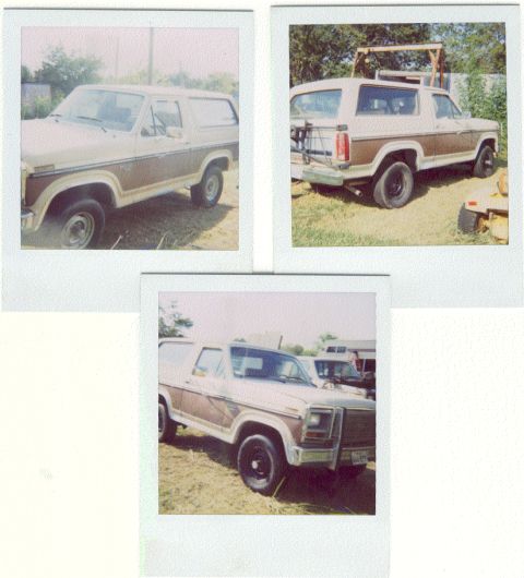
1986 Ford Bronco/
Photo
supermotors.net/registry/media/1120989
Ford Bronco Transmission Crossmember & Mount Insulator Exploded Diagram - Later Models

Exploded parts diagram of a transmission mount assembly labeling the insulator, screw, nut and washer, and gusset.
This is a partial page scan from an automotive repair manual (Haynes-style formatting) showing an exploded parts diagram of a transmission mount/crossmember assembly. The visible illustration depicts the transmission mount insulator, its attaching screw, nut-and-washer hardware, and a left-hand (LH) gusset, with dashed alignment lines showing how the fasteners pass through the crossmember. A partial caption at the edge of the page reads '…ember assembly details - later models,' indicating this is the crossmember assembly detail for later-model vehicles. The visible procedural text (steps 12 and 13) covers transmission removal: step 12 instructs on 5-speed models to remove bolts retaining a component from the transmission (referencing Chapter 5), and step 13 instructs to support the transmission with a transmission jack, ensuring the transmission is securely fastened to the jack. References to Chapter 7C (transmission extension housing/case) are also visible. The scan is cropped, cutting off portions of the text column and the second exploded diagram at the bottom, so complete step text is not readable.
Is this accurate? Sign in to help verify it.
Frequently asked questions
- What parts are shown in the transmission crossmember exploded diagram?
- The diagram labels an INSULATOR (transmission mount), a SCREW, NUT AND WASHER hardware, and a GUSSET (LH) attached to the crossmember.
- How should the transmission be supported during removal according to this page?
- Step 13 says to support the transmission with a transmission jack and make sure the transmission is securely fastened to the jack.
- What extra step applies to 5-speed models?
- Step 12 states that on 5-speed models you must remove the bolts retaining a component from the transmission (see Chapter 5); the full sentence is cut off in the scan.
- Which models does the crossmember diagram apply to?
- The partial caption reads '…ember assembly details - later models,' indicating the exploded view applies to later models.
Comments
More from this build




No comments yet.