Home/
Registry/
Ford/
Bronco/
1980-1986/
1986 Ford Bronco/
Photo
supermotors.net/registry/media/1120988
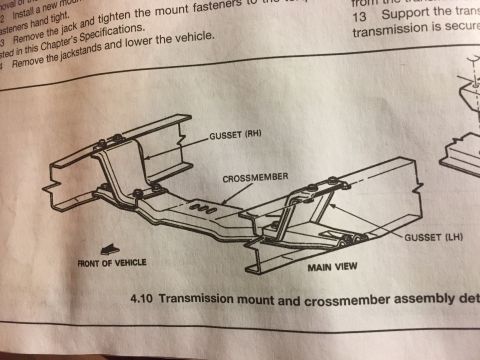
Ford Bronco Transmission Mount & Crossmember Assembly Diagram (Fig 4.10)

Reference · 1980-1986 BroncoAll 40 service procedures

Service procedure with figure 4.10 detailing transmission mount and crossmember assembly with gussets and crossmember.
Part of 1980-1986 Ford Bronco Service Procedures
This is a partial scan of a page from a repair manual (likely a Haynes-style manual) showing a section of a transmission mount removal and installation procedure. The visible text includes procedure steps: installing a new mount with fasteners hand tight, removing the jack and tightening the mount fasteners to the torque listed in the Chapter's Specifications, and removing the jackstands and lowering the vehicle. A separate numbered step (13) from an adjacent procedure instructs supporting the transmission. The main content is an exploded line-art illustration labeled figure 4.10, 'Transmission mount and crossmember assembly details,' showing the transmission crossmember mounted between two frame rails. Callouts identify the right-hand gusset (GUSSET RH), the CROSSMEMBER itself, and the left-hand gusset (GUSSET LH), with an arrow indicating FRONT OF VEHICLE and the drawing labeled MAIN VIEW. A reader can learn how the transmission crossmember attaches to the frame rails via left and right gussets with bolted fasteners, and the general sequence for reinstalling a transmission mount. No torque values, part numbers, year ranges, or model identification appear on this visible portion of the page.
Is this accurate? Sign in to help verify it.
Frequently asked questions
- What does figure 4.10 show?
- Figure 4.10 shows the transmission mount and crossmember assembly details, illustrating the crossmember bolted between the frame rails with right-hand (RH) and left-hand (LH) gussets, viewed from the front of the vehicle in a 'main view' drawing.
- How is the crossmember attached to the frame?
- The illustration shows the crossmember attached to the frame rails through left-hand and right-hand gussets secured with bolted fasteners.
- What is the procedure for finishing transmission mount installation?
- Per the visible steps: install the new mount with fasteners hand tight, remove the jack and tighten the mount fasteners to the torque listed in the Chapter's Specifications, then remove the jackstands and lower the vehicle.
- Where are the torque specifications for the mount fasteners?
- The document refers the reader to the torque values listed in 'this Chapter's Specifications'; the actual values are not shown on this page.
No comments yet.