Home/
Registry/
Ford/
Bronco/
1992-1996/
“Little Bronco”/
Photo
supermotors.net/registry/media/1143322
1992-95 Ford Bronco/F-Series 5.0L 5.8L & 1991 7.5L Engine Wiring Diagrams
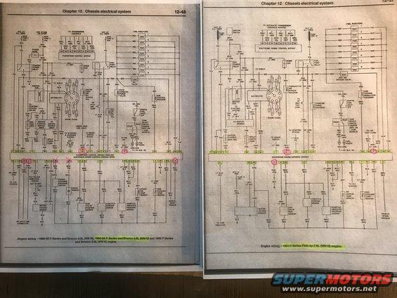
Photographed repair-manual pages showing full engine wiring diagrams with connectors and circuits for F-Series and Bronco trucks.
This scan shows two facing pages from a Haynes-style repair manual, Chapter 12 (Chassis electrical system), containing full engine-compartment wiring diagrams for Ford full-size trucks. The left page (12-43) is the engine wiring diagram for 1992-93 F-Series and Bronco 5.0L (VIN N), 1992-94 F-Series and Bronco 5.8L (VIN H), and 1995 F-Series and Bronco 5.8L (VIN H) engines, centered on the Powertrain Control Module (1993-95)/Electronic Engine Control Module (1992) with numbered connector pins. The right page covers the 1991 F-Series Pick-up 7.5L (VIN G) engine. Both diagrams trace circuits for the fuel injectors (1-8), fuel pump relay and dual fuel pumps, tank select switch, ignition coil, distributor/TFI ignition module, EGR control/vacuum regulator solenoid, EVAP canister purge valve, inertia fuel shut-off switch, idle air bypass/IAC valve, oxygen sensor, throttle position, MAP, air/engine coolant temperature, knock and vehicle speed sensors, plus power feeds (Maxi Fuses I 30A, U 20A, O 20A; fuse links N and W; Fuse E 15A; Fuse 5 15A) and wire color codes throughout. Several EEC connector pin numbers (e.g., 31, 17, 9, 51, 6) are circled in pink by the uploader, likely marking circuits under diagnosis. Reader can identify wire colors and pin assignments for engine control circuits.
Is this accurate? Sign in to help verify it.
Frequently asked questions
- Which vehicles does the left wiring diagram (page 12-43) cover?
- It covers engine wiring for 1992-93 F-Series and Bronco 5.0L (VIN N), 1992-94 F-Series and Bronco 5.8L (VIN H), and 1995 F-Series and Bronco 5.8L (VIN H) engines.
- What engine does the right-hand diagram apply to?
- Engine wiring for the 1991 F-Series Pick-up 7.5L (VIN G) engine.
- What power feeds and fuses are shown for the 1992-95 diagram?
- MAXI FUSE I 30A (hot at all times), MAXI FUSE U 20A (hot in run or start), MAXI FUSE O 20A (hot at all times), and Fuse E 15A (hot in run). The 1991 diagram uses Fuse Link N, Fuse Link W, and Fuse 5 15A.
- How is the dual fuel tank setup shown?
- Both diagrams show a Tank Select Switch with FRONT and REAR positions feeding two fuel pumps, with a note that a jumper is used on 1-tank models.
- What module do the engine circuits connect to?
- On the 1992-95 diagram, the Powertrain Control Module (1993-95)/Electronic Engine Control Module (1992); on the 1991 diagram, the Electronic Engine Control Module, both shown with numbered connector pins.
Comments
More from this build






No comments yet.