Home/
Registry/
Ford/
Probe/
1993-1997/
“Bonneville Dreamer”/
Photo
supermotors.net/registry/media/916421
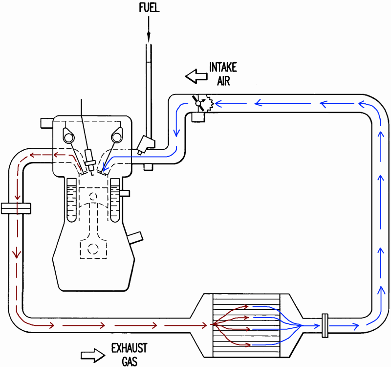
Exhaust Venturi Turbo Flow Schematic - Intake Air, Fuel & Exhaust Gas Diagram
Reference · 1993-1997 ProbeAll 25 schematics
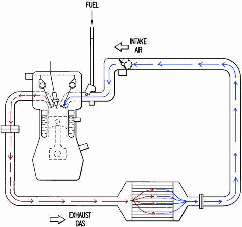
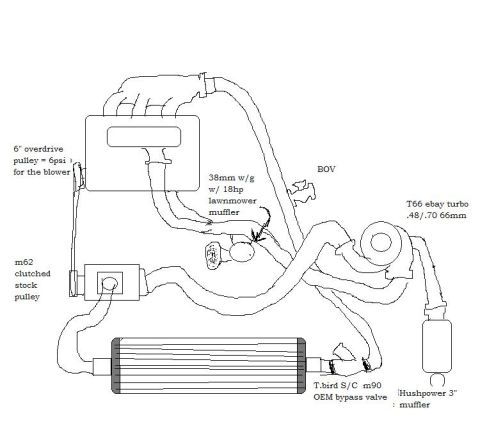
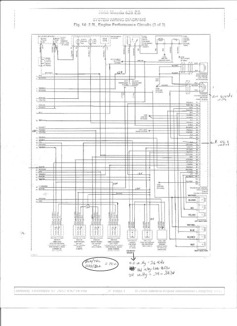

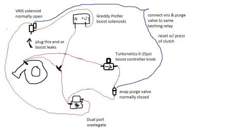
Schematic of combustion airflow showing fuel and intake air entering the cylinder and exhaust gas recirculation routing.
Part of 1993-1997 Ford Probe Schematics
This document is a conceptual schematic (not a text-based reference) showing gas flow paths through an engine system. Only three text labels appear: FUEL, INTAKE AIR, and EXHAUST GAS. The drawing depicts a single-cylinder piston engine in cross-section with a fuel delivery line entering from above. Intake air (traced with blue arrows) enters at the upper right through a small valve or throttle mechanism and flows into the engine's intake port. Exhaust gas (traced with red/dark arrows) exits the engine on the left side and travels through a pipe along the bottom of the diagram into a finned, cylindrical device resembling a heat exchanger or venturi/ejector unit. Inside this device the exhaust arrows fan out and interact with the incoming intake air stream, which loops up the right side of the page back to the intake. The diagram illustrates how exhaust gas energy is used to drive or entrain intake air, consistent with the uploader's filename 'Exhaust_Venturi_Turbo', suggesting an exhaust-driven venturi/turbocharging concept. There are no part numbers, fuse data, wire colors, torque specs, model years, or vehicle-specific information anywhere in the image; it is purely an illustrative flow schematic.
Is this accurate? Sign in to help verify it.
Frequently asked questions
- What does this schematic show?
- It shows a piston engine with three labeled flows: FUEL entering from the top, INTAKE AIR entering at the upper right (blue arrows), and EXHAUST GAS exiting on the left (red arrows) into a finned device at the bottom right where the exhaust and intake air streams interact.
- Where does the intake air enter in this diagram?
- Intake air enters at the upper right through a small valve/throttle device and follows the blue arrows into the engine's intake; a second blue path loops around the right side from the finned device back toward the intake.
- What happens to the exhaust gas in the diagram?
- Exhaust gas (red arrows) leaves the left side of the engine, travels through a pipe along the bottom, and fans out inside a finned cylindrical device where it meets the intake air flow path.
- Does this document identify a specific vehicle, year, or part numbers?
- No. The only text visible is FUEL, INTAKE AIR, and EXHAUST GAS. There are no vehicle model, year, or part number references.
No comments yet.