60-2 Crank Trigger Wheel Diagram - Tooth Positions A/B/C, VR Sensor Alignment

Reference · 1993-1997 ProbeAll 25 schematics
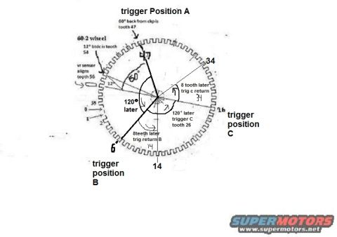
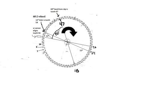
Hand-drawn schematic of a 60-2 crank trigger wheel labeling trigger positions A, B and C with tooth counts and degree offsets for timing.
Part of 1993-1997 Ford Probe Schematics
This hand-annotated schematic shows a 60-2 (60-minus-2) crankshaft trigger wheel and how its teeth relate to ignition/timing trigger positions. The wheel diagram is labeled with tooth numbers around its circumference (0, 1, 2, up to 59), with a two-tooth gap implied by the '60-2 wheel' label. Key annotations state that 12° BTDC corresponds to tooth 54, the VR (variable reluctance) sensor aligns with tooth 56, and 60° back from the CKP reference is tooth 47, marked as 'trigger Position A'. From Position A, the diagram indicates '120° later' arriving at trigger position B (near tooth 6/14 area), and another '120° later trigger C tooth 26' for trigger position C. It also notes trigger return points: '8 teeth later trig return B' and '8 tooth later trig c return' (near tooth 34), showing the pulse width of each trigger event as 8 teeth. A reader can learn the angular relationships between the three trigger positions (A, B, C) spaced 120° apart on the 60-2 wheel, which teeth correspond to each event, and the sensor alignment reference, useful for setting up aftermarket engine management or understanding a distributorless ignition trigger scheme on this owner's 1993 Ford Probe project.
Is this accurate? Sign in to help verify it.
Frequently asked questions
- Which tooth on the 60-2 wheel corresponds to 12° BTDC?
- The diagram states that 12° BTDC is tooth 54.
- Which tooth does the VR sensor align with?
- The VR sensor aligns with tooth 56.
- Where is trigger Position A on the 60-2 wheel?
- Trigger Position A is 60° back from the CKP reference, at tooth 47.
- How far apart are trigger positions A, B, and C?
- They are spaced 120° apart: 120° after Position A comes trigger position B, and 120° later trigger C occurs at tooth 26.
- How long does each trigger event last on this wheel?
- The trigger returns 8 teeth later, the diagram notes '8 teeth later trig return B' and '8 tooth later trig c return' (near tooth 34).
No comments yet.