MegaSquirt DB37 & DB9 Connector Schematic - Pinout, Jumpers & Test Voltages
Reference · 1993-1997 ProbeAll 25 schematics
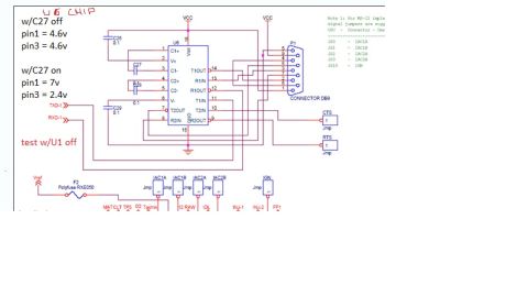
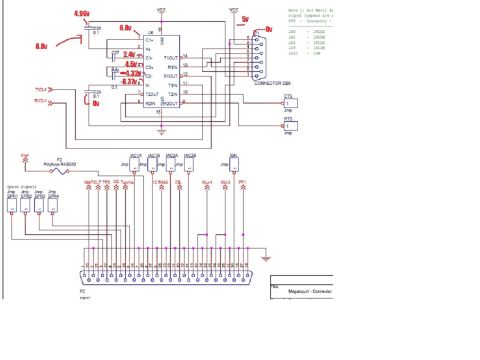
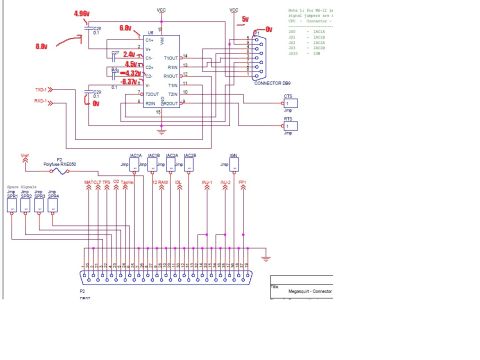










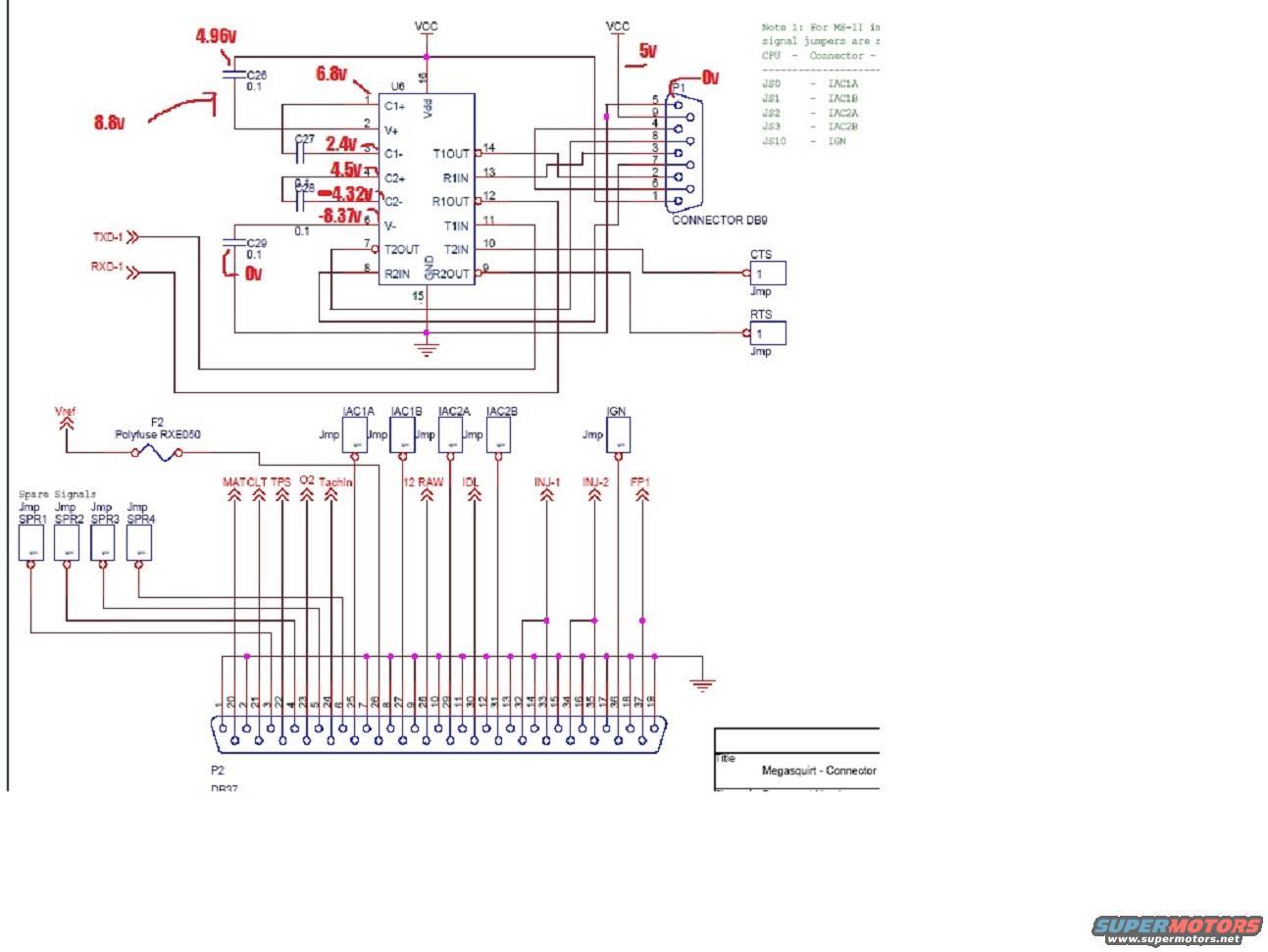
Megasquirt ECU connector schematic showing the DB9 serial port, MAX232 level converter and DB37 main input/output connector.
Part of 1993-1997 Ford Probe Schematics
This document is a schematic page titled "Megasquirt - Connector," showing the connector and serial-communication section of a MegaSquirt DIY engine management (EFI) controller. It depicts U6, a 16-pin RS-232 level-shifter IC (with pins C1+/C1-, C2+/C2-, V+, V-, T1OUT/T1IN, R1IN/R1OUT, T2OUT/T2IN, R2IN/R2OUT, Vdd, GND) with its charge-pump capacitors C26-C29 (0.1 µF), connected to the DB9 serial connector P1 and TXD-1/RXD-1 lines, plus CTS and RTS jumpers. Hand-marked voltage measurements in red (4.96v, 8.8v, 6.8v, 2.4v, 4.5v, -4.32v, -8.37v, 0v, 5v) annotate test points around the IC, suggesting the scan was used for troubleshooting the serial circuit. The lower section shows the main P2 DB37 connector with all 37 pins numbered and wired to signals including MAT, CLT, TPS, O2, TachIn, 12 RAW, IDL, INJ-1, INJ-2, FP1, IGN, IAC1A/IAC1B/IAC2A/IAC2B idle-air-control jumpers, spare signal jumpers SPR1-SPR4, and Vref fed through polyfuse F2 (RXE050). A partially cut-off note explains that for MS-II, signal jumpers JS0-JS3 and JS10 map to IAC1A, IAC1B, IAC2A, IAC2B, and IGN. The page is a reference for wiring or diagnosing the MegaSquirt DB37 harness connector.
Is this accurate? Sign in to help verify it.
Frequently asked questions
- What jumpers map to the IAC and IGN signals on MS-II?
- Per Note 1: JS0 = IAC1A, JS1 = IAC1B, JS2 = IAC2A, JS3 = IAC2B, and JS10 = IGN.
- What protects the Vref line on the MegaSquirt connector?
- Vref runs through F2, a Polyfuse type RXE050, before reaching the DB37 connector.
- What signals go to the DB37 (P2) connector?
- The schematic shows MAT, CLT, TPS, O2, TachIn, 12 RAW, IDL, INJ-1, INJ-2, FP1, IGN, IAC1A/IAC1B/IAC2A/IAC2B, spare signals SPR1-SPR4, and Vref connecting to the 37-pin P2 connector.
- What capacitors are used around U6 in the serial circuit?
- C26, C27, C28, and C29 are shown, marked 0.1 (µF), connected to the C1+/C1-, C2+/C2-, V+ and V- charge-pump pins of U6.
- What voltages were measured on the U6 charge-pump pins?
- Handwritten measurements show 4.96v at C26, 8.8v, 6.8v at pin 1 (C1+), 2.4v at C1-, 4.5v at C2+, -4.32v at C2-, -8.37v at V-, 0v at C29/R2IN, 5v at VCC, and 0v at P1.






No comments yet.