Home/
Registry/
Ford/
Bronco/
1978-1979/
1978 Ford Bronco/
Photo
supermotors.net/registry/media/134603
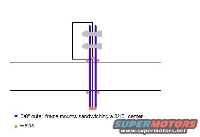
Frame Mount Schematic - 3/8" Outer Plates Sandwiching 3/16" Center, Weld Points
Reference · 1978-1979 BroncoAll 44 schematics








Fabrication schematic of 3/8 inch outer frame mounts sandwiching a 3/16 inch center plate, with weld locations marked.
Part of 1978-1979 Ford Bronco Schematics
This document is a simple hand-drawn schematic (uploaded as "frame-mount.JPG") illustrating a fabricated frame mount design, apparently for rock sliders or a similar bolt-on/weld-on accessory. The drawing shows two vertical purple plates labeled as 3/8"-thick outer frame mounts that sandwich a 3/16"-thick center piece. The assembly passes across two horizontal lines representing frame rails or tubing, and small orange marks in the legend indicate weld locations where the vertical mounts join the horizontal members. Gray hardware symbols near the top of the drawing depict bolts clamping the sandwiched plates together, with a rectangular outline suggesting the frame or body section being attached to. The legend contains only two entries: the purple color identifies the "3/8" outer frame mounts sandwiching a 3/16" center," and the orange color identifies "welds." No dimensions beyond material thickness, no part numbers, torque values, or vehicle-specific applicability information are shown. A reader can learn the basic construction concept: use two 3/8" outer plates bolted around a 3/16" center plate, then weld the assembly to the horizontal structure at the indicated points. The companion file in the album (dodge-ram-sliders.JPG) suggests this relates to a slider mounting project.
Is this accurate? Sign in to help verify it.
Frequently asked questions
- What thickness steel is used for the outer frame mounts?
- The outer frame mounts are 3/8" thick, shown in purple in the diagram.
- What thickness is the center piece being sandwiched?
- The center piece is 3/16" thick, sandwiched between the two 3/8" outer frame mounts.
- Where are the welds located in this frame mount design?
- The orange marks in the diagram indicate welds where the vertical mount plates meet the two horizontal frame members.
- How is the mount assembly fastened besides welding?
- The diagram shows bolts (gray hardware symbols) clamping the sandwiched plates together near the top of the mount.






No comments yet.