Home/
Registry/
Ford/
Bronco/
1987-1991/
1991 Ford Bronco/
Photo
supermotors.net/registry/media/167603
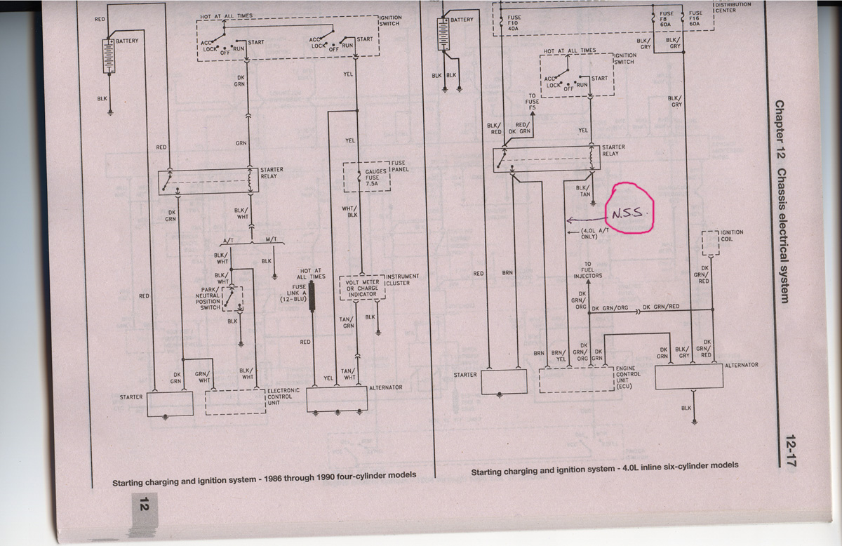
Starting, Charging & Ignition Wiring Diagram 1986-90 4-Cyl & 4.0L Inline Six
Reference · 1987-1991 BroncoAll 175 wiring diagrams


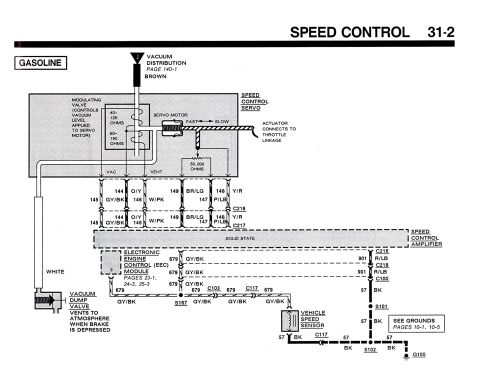
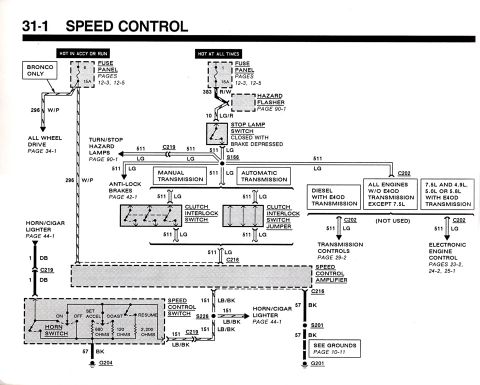
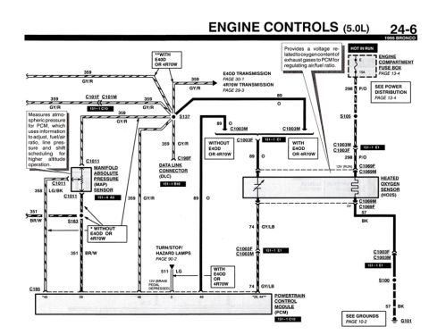
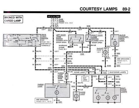











Wiring diagram of the starting, charging and ignition system for four-cylinder and 4.0L inline six-cylinder models with color-coded wires.
Part of 1987-1991 Ford Bronco Wiring Diagrams
This is a scanned page (12-17) from Chapter 12, 'Chassis electrical system,' of a repair manual, showing two starting, charging and ignition system wiring diagrams. The left diagram covers 1986 through 1990 four-cylinder models and traces circuits from the battery through the ignition switch (ACC/LOCK/OFF/RUN/START), starter relay, park/neutral position switch (with A/T and M/T variants), 7.5A gauges fuse in the fuse panel, fuse link A (12-BLU), instrument cluster volt meter or charge indicator, starter, electronic control unit, and alternator, with wire colors such as DK GRN, YEL, BLK/WHT, TAN/GRN, and GRN/WHT. The right diagram covers 4.0L inline six-cylinder models and shows the battery, distribution center fuses F8 (60A) and F16 (60A), fuse F10 (40A), ignition switch, starter relay, ignition coil, fuel injector feed (DK GRN/ORG), engine control unit (ECU), starter, and alternator, with wire colors including BLK/GRY, BLK/TAN, RED/DK GRN, BRN/YEL, and DK GRN/RED. A hand-drawn pink circle with the notation 'N.S.S.' points to the wire marked '(4.0L A/T ONLY)' from the starter relay, highlighting the neutral safety switch circuit. A reader can identify fuse ratings, wire colors, and component interconnections for these starting/charging circuits.
This document covers 1986-1990, which may differ from this 1991 Ford Bronco.
Is this accurate? Sign in to help verify it.
Frequently asked questions
- What fuse ratings are shown in the 4.0L inline six-cylinder starting/charging diagram?
- Fuse F10 is 40A, and fuses F8 and F16 in the distribution center are each 60A. A 'TO FUSE F5' branch is also shown from the ignition switch.
- What fuse protects the gauges circuit on 1986-1990 four-cylinder models?
- A 7.5A GAUGES fuse in the fuse panel, feeding a WHT/BLK wire toward the instrument cluster volt meter or charge indicator.
- What does the hand-written 'N.S.S.' annotation point to?
- It is circled in pink and points with an arrow to the wire from the starter relay labeled '(4.0L A/T ONLY),' identifying the neutral safety switch circuit on 4.0L automatic transmission models.
- What wire color feeds the fuel injectors on the 4.0L diagram?
- DK GRN/ORG (dark green/orange), branching to the fuel injectors, with a DK GRN/RED branch going to the ignition coil.
- What fuse link is shown on the four-cylinder charging circuit?
- Fuse Link A (12-BLU), fed from a 'HOT AT ALL TIMES' source on a RED wire toward the alternator/ECU circuit.






No comments yet.