Home/
Registry/
Ford/
Bronco/
1987-1991/
1991 Ford Bronco/
Photo
supermotors.net/registry/media/192435
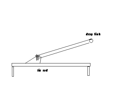
Ford Bronco Steering Linkage Schematic - Drag Link & Tie Rod Layout
Reference · 1987-1991 BroncoAll 112 schematics













Schematic line drawing illustrating a steering tie rod and drag link arrangement.
Part of 1987-1991 Ford Bronco Schematics
This document is a very simple hand-drawn (CAD-style) line schematic depicting a steering linkage arrangement. It shows a horizontal tie rod supported at both ends, with a drag link attached at a pivot/joint point near the left-center of the tie rod and angling upward to the right, terminating in a circular end (representing a ball or socket end). Only two text labels appear: "drag link" identifying the angled rod, and "tie rod" identifying the horizontal bar. Based on the uploader's filename ("untover kncukcle steering.jpg"), the drawing appears intended to illustrate an inverted-Y or over/under-the-knuckle style steering linkage geometry, likely as part of a discussion of steering setups on a solid-axle Ford Bronco, though the drawing itself contains no year, make, model, part numbers, dimensions, or torque specifications. A reader can learn only the basic geometric relationship between the drag link and tie rod in this configuration, specifically that the drag link connects to the tie rod (rather than directly to a knuckle) and rises at an angle from that connection point. No other technical data is present in the image.
Is this accurate? Sign in to help verify it.
Frequently asked questions
- What components are labeled in this steering schematic?
- Only two components are labeled: the "drag link" (the angled rod rising to the upper right) and the "tie rod" (the horizontal bar).
- How does the drag link connect in this diagram?
- The drag link attaches at a joint near the left-center of the tie rod and angles upward to the right, ending in a circular (ball-type) end.
- Does this diagram include any measurements, torque specs, or part numbers?
- No. The drawing contains only the two labels "drag link" and "tie rod" with no dimensions, torque values, or part numbers.






No comments yet.