Home/
Registry/
Ford/
Bronco/
1992-1996/
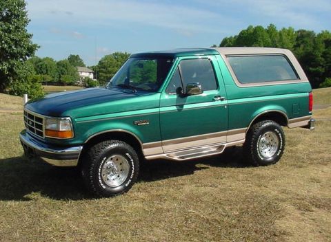
1996 Ford Bronco/
Photo
supermotors.net/registry/media/288703
1996 Ford Bronco Radio & Speaker Wiring Diagram - AM/FM Cassette Wire Colors

Reference · 1992-1996 BroncoAll 411 wiring diagrams
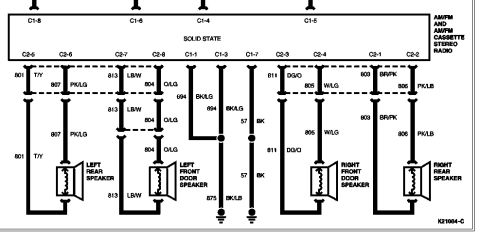

Wiring diagram of an AM/FM cassette stereo radio connected to four speakers with color-coded wires and connector pin labels.
Part of 1992-1996 Ford Bronco Wiring Diagrams
This document is a factory-style wiring diagram for the AM/FM and AM/FM cassette stereo radio (labeled 'solid state') and its four speakers. It shows the radio unit with two connectors (C1 and C2) and identifies each pin: C1-8, C1-6, C1-4, C1-5 across the top, and C2-5, C2-6, C2-7, C2-8, C1-1, C1-3, C1-7, C2-3, C2-4, C2-1, C2-2 across the bottom. Each speaker wire is identified by circuit number and color code: the left rear speaker uses 801 T/Y and 807 PK/LG; the left front door speaker uses 813 LB/W and 804 O/LG; the right front door speaker uses 811 DG/O and 805 W/LG; the right rear speaker uses 803 BR/PK and 806 PK/LB. Grounding circuits 694 BK/LG (from C1-1 and C1-3), 875 BK/LB, and 57 BK (from C1-7) run to ground points at the bottom of the diagram. The diagram carries reference number K21064-C. A reader can use this to identify which radio connector pin and wire color feeds each speaker, useful for radio replacement, speaker upgrades, or troubleshooting audio wiring faults.
Is this accurate? Sign in to help verify it.
Frequently asked questions
- What wire colors go to the left rear speaker?
- The left rear speaker uses circuit 801 T/Y (from pin C2-5) and circuit 807 PK/LG (from pin C2-6).
- Which radio pins feed the right front door speaker?
- Pins C2-3 (circuit 811, DG/O) and C2-4 (circuit 805, W/LG) connect the radio to the right front door speaker.
- What are the radio's ground wires?
- The diagram shows ground circuits 694 BK/LG (from C1-1 and C1-3), which joins 875 BK/LB to ground, and circuit 57 BK from pin C1-7 to ground.
- What wires connect the right rear speaker?
- Circuit 803 BR/PK (from pin C2-1) and circuit 806 PK/LB (from pin C2-2) run to the right rear speaker.
- What radios does this diagram cover?
- It is labeled for the AM/FM and AM/FM cassette stereo radio (solid state), diagram reference K21064-C.



No comments yet.