Home/
Registry/
Ford/
Bronco/
1987-1991/
1991 Ford Bronco/
Photo
supermotors.net/registry/media/300777
Ford Hydro-Boost Plumbing Diagram - MotorHome & Commercial Chassis Hose Routing

Reference · 1987-1991 BroncoAll 61 exploded parts diagrams
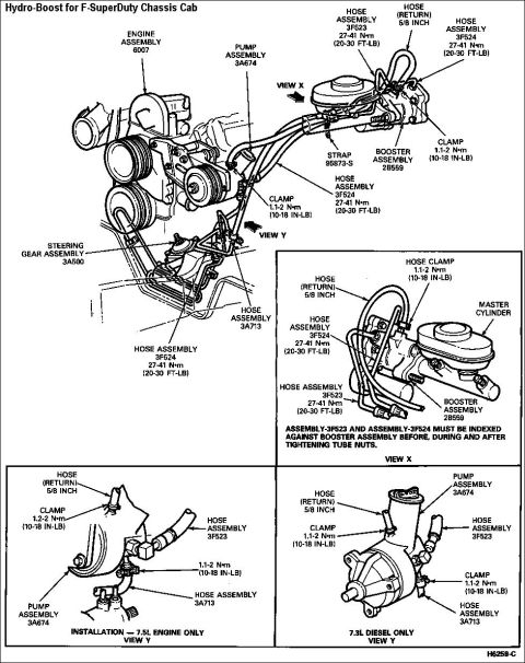
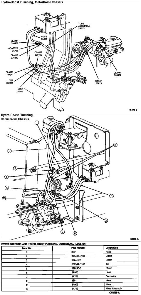

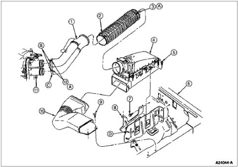
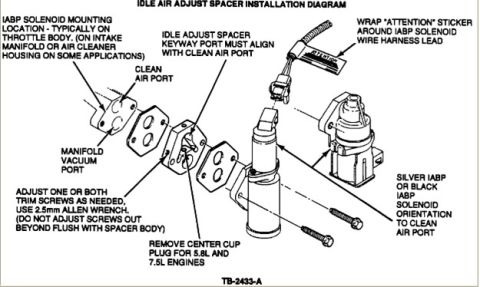
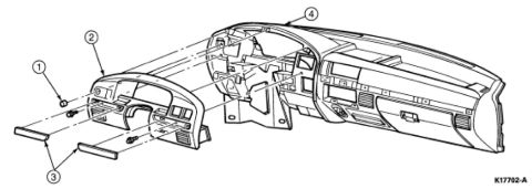
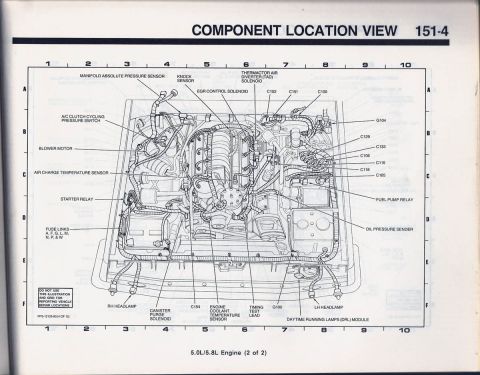
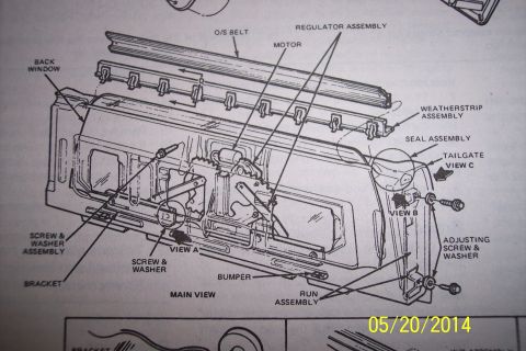
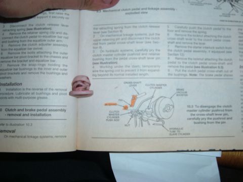
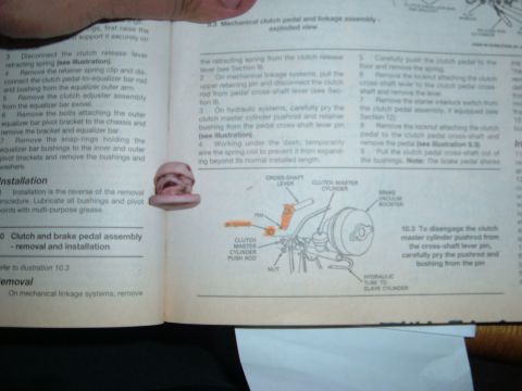






Power steering and Hydro-Boost plumbing diagrams for motorhome and commercial chassis with numbered callouts and a part-number legend.
Part of 1987-1991 Ford Bronco Exploded Parts Diagrams
This scanned reference page shows two exploded/routing diagrams for Hydro-Boost power steering and brake booster plumbing on Ford chassis. The upper diagram, labeled 'Hydro-Boost Plumbing, MotorHome Chassis' (figure H6071-B), illustrates hose and tube routing between the power steering reservoir, power steering pump, Hydro-Boost unit, and master cylinder, with callouts identifying components by base part number: hose 3A005, tube assembly 3A713, clamps 390462, 376240, and 97241, adapter 3A766, tee 389344, and strap 95873. The lower diagram, 'Hydro-Boost Plumbing, Commercial Chassis' (figure H8195-A), uses circled item numbers 1-10 keyed to a legend table titled 'POWER STEERING AND HYDRO-BOOST PLUMBING, COMMERCIAL (LEGEND)' (CH8196-A). The legend lists: item 1 hose 3691, item 2 clamp 390462-S100, item 3 clamp 97241-S8, item 4 tee 389344-S100, item 5 clamp 376240-S, item 6 hose 3A005, item 7 connector 3A766, item 8 hose 3691, item 9 hose 3A005, and item 10 hose assembly 3A713. A reader can learn the correct hose routing, clamp locations, and Ford part number designations needed to service or replace Hydro-Boost plumbing on MotorHome and Commercial chassis applications.
Is this accurate? Sign in to help verify it.
Frequently asked questions
- What part number is the Hydro-Boost hose assembly on the Commercial chassis?
- Item 10 in the legend is hose assembly 3A713; it also appears as 'TUBE ASSEMBLY 3A713' in the MotorHome chassis diagram.
- What clamps are used in the Hydro-Boost plumbing?
- The legend lists clamp 390462-S100 (item 2), clamp 97241-S8 (item 3), and clamp 376240-S (item 5). The MotorHome diagram shows clamps 390462, 376240, and 97241 at multiple locations.
- What is part number 3A766?
- In the Commercial legend it is item 7, a connector; in the MotorHome diagram it is labeled 'ADAPTER 3A766'.
- Which hoses are used in the Commercial chassis Hydro-Boost plumbing?
- Hose 3691 (items 1 and 8) and hose 3A005 (items 6 and 9), plus hose assembly 3A713 (item 10).
- What tee fitting is used in the Hydro-Boost lines?
- Tee 389344 (Commercial legend item 4, part number 389344-S100).






No comments yet.