Custom Rear Radius Arm / Link Suspension Sketch - Heim Joints & 2" OD Tube Plan

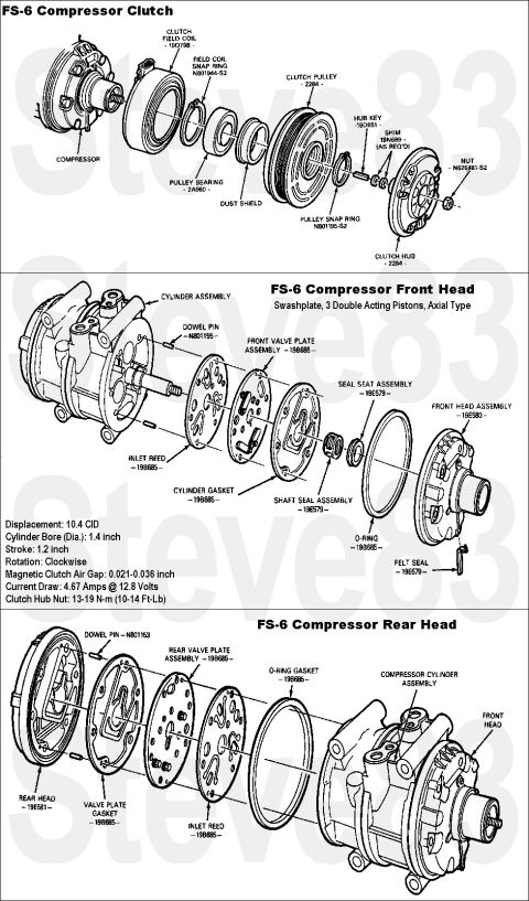
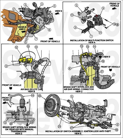
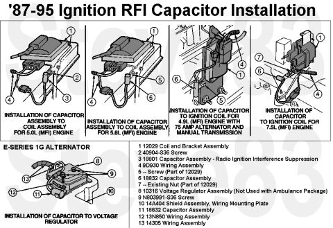
Reference · 1980-1986 BroncoAll 61 exploded parts diagrams
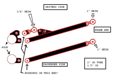







Labeled assembly diagram of driver/passenger-side suspension links showing axle mounts, heim joints, frame ends, and 2-inch OD tube.
Part of 1980-1986 Ford Bronco Exploded Parts Diagrams
This is a homemade concept sketch (not a factory document) illustrating a planned rear suspension link/radius arm setup, uploaded to a 1984 Ford Bronco gallery as "rear arms4.JPG". The drawing shows two long link arms labeled "DRIVERS SIDE" and "PASSENGER SIDE", drawn in black tube with red-outlined ends. Each arm's frame end is labeled "1" HEIM", indicating 1-inch heim (rod end) joints at the frame mounting points, with a callout box reading "FRAME END". The driver's side arm shows a secondary upper link or wishbone mount using a "3/4" HEIM". Two round shapes on the left are labeled "AXLE", representing the axle tube ends with mounting brackets. The axle ends of both arms carry the handwritten question "BUSHINGS ON THIS END?", indicating the builder is deciding between bushings and heims at the axle side. A specification box notes the arm material: "2" OD TUBE, 1.5" ID" (2-inch outside diameter tubing with 1.5-inch inside diameter, i.e., 0.25" wall). The sketch conveys planned joint sizes, tube dimensions, and mounting orientation for a custom long-arm or link-style rear suspension conversion, but contains no part numbers, torque specs, or year/model applicability information.
Is this accurate? Sign in to help verify it.
Frequently asked questions
- What size heim joints are used at the frame end of the arms?
- The diagram labels the frame end of both the driver's side and passenger side arms with 1" HEIM joints.
- What size is the smaller heim joint shown on the driver's side arm?
- A 3/4" HEIM is called out on the upper mount of the driver's side arm.
- What tubing is specified for the link arms?
- The diagram specifies 2" OD tube with 1.5" ID (0.25" wall thickness).
- What joint is used at the axle end of the arms?
- The diagram leaves this undecided, with the note 'BUSHINGS ON THIS END?' pointing to the axle ends of both arms.
- What do the round shapes on the left of the drawing represent?
- They are labeled 'AXLE' and represent the axle tube ends with the link mounting brackets.






No comments yet.