Home/
Registry/
Ford/
Probe/
1993-1997/
1994 Ford Probe/
Photo
supermotors.net/registry/media/544583
Ford T92C-6000-AH Breakout Box Adapter Instructions - 1993 Probe 2.0L & 2.5L

Reference · 1993-1997 ProbeAll 13 service procedures
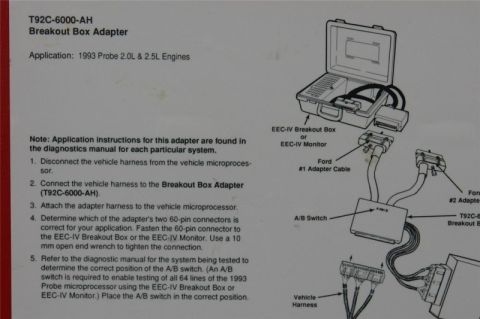
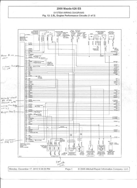
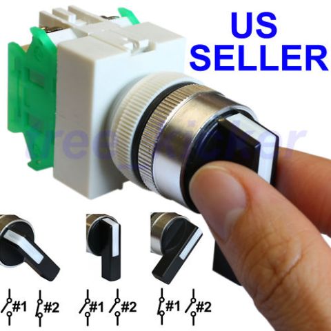
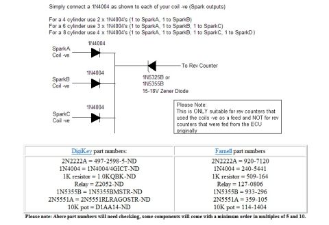
Step-by-step instructions for connecting the EEC-IV Breakout Box Adapter on 1993 Probe engines, with a wiring connection diagram.
Part of 1993-1997 Ford Probe Service Procedures
This document is an instruction sheet for the Ford T92C-6000-AH Breakout Box Adapter, stated as applicable to 1993 Probe 2.0L and 2.5L engines. It explains how to connect the adapter between the vehicle wiring harness and the vehicle microprocessor (ECU) so that diagnostics can be performed with an EEC-IV Breakout Box or EEC-IV Monitor. The five-step procedure directs the technician to: disconnect the vehicle harness from the microprocessor; connect the harness to the Breakout Box Adapter; attach the adapter harness to the microprocessor; select the correct one of the adapter's two 60-pin connectors and fasten it to the EEC-IV Breakout Box or Monitor using a 10 mm open end wrench; and set the A/B switch to the correct position per the diagnostic manual. The sheet notes that the A/B switch is required to enable testing of all 64 lines of the 1993 Probe microprocessor, and that detailed application instructions are in the diagnostics manual for each system. An illustration shows the breakout box, Ford #1 and #2 adapter cables, the A/B switch box, the T92C breakout box adapter, and the vehicle harness connections.
This document covers 1993, which may differ from this 1994 Ford Probe.
Is this accurate? Sign in to help verify it.
Frequently asked questions
- What vehicles does the T92C-6000-AH Breakout Box Adapter apply to?
- The document states its application is 1993 Probe 2.0L & 2.5L engines.
- How do I connect the T92C-6000-AH adapter for diagnostics?
- Disconnect the vehicle harness from the vehicle microprocessor, connect the harness to the Breakout Box Adapter (T92C-6000-AH), attach the adapter harness to the microprocessor, fasten the correct 60-pin connector to the EEC-IV Breakout Box or EEC-IV Monitor, then set the A/B switch per the diagnostic manual.
- What tool is needed to tighten the 60-pin connector?
- A 10 mm open end wrench is used to tighten the 60-pin connection to the EEC-IV Breakout Box or EEC-IV Monitor.
- Why is the A/B switch required?
- The A/B switch is required to enable testing of all 64 lines of the 1993 Probe microprocessor when using the EEC-IV Breakout Box or EEC-IV Monitor.
- Where are the detailed application instructions for this adapter found?
- In the diagnostics manual for each particular system, per the note on the sheet.



No comments yet.