CB Radio Inline Power Noise Filter Schematic - RC Filter Diagram

Reference · 1987-1991 BroncoAll 110 schematics
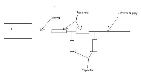














Hand-drawn electrical circuit schematic showing a CB connected through resistors and a capacitor to a power supply.
Part of 1987-1991 Ford Bronco Schematics
This document is a simple hand-drawn electrical schematic (uploaded as "inlinefilter.JPG") showing an in-line power filter for a CB radio installation. On the left is a box labeled "CB" (the CB radio). Its power lead runs to the right through two series resistors and continues to a point labeled "2 Power Supply" (the power source). Two capacitors are shown connected from the power line downward (to ground, implied): one placed between the two resistors and one after the second resistor, forming a classic RC (resistor-capacitor) low-pass noise filter arrangement. The diagram carries no component values, part numbers, wire colors, or vehicle-specific information, only the five text labels: CB, Power, Resistors, 2 Power Supply, and Capacitor. A reader can learn the general topology for building an in-line noise filter to clean up the power feed to a CB radio: series resistors in the supply line with shunt capacitors after each resistor stage. It was uploaded to a 1988 Ford Bronco gallery, but the drawing itself is generic and contains nothing tying it to any particular vehicle, year, or model.
Is this accurate? Sign in to help verify it.
Frequently asked questions
- What does this schematic show?
- An in-line filter on the power lead of a CB radio: the power line runs from the CB through two series resistors to the power supply, with two capacitors connected off the line (one between the resistors and one after the second resistor).
- How many resistors and capacitors are used in this filter?
- Two resistors in series along the power line and two capacitors, one placed between the resistors and one after the second resistor.
- Where do the capacitors connect in the circuit?
- They hang off the power line: the first between the two series resistors and the second between the last resistor and the power supply side.
- Does the diagram give component values or part numbers?
- No. It only labels the parts generically as Resistors and Capacitor, with no values, ratings, or part numbers shown.






No comments yet.