Home/
Registry/
Ford/
Bronco/
1987-1991/
1988 Ford Bronco/
Photo
supermotors.net/registry/media/610942
Fog/Driving Light Relay Wiring Diagram - 55W Aux Lights, Relay Pins 30/85/86/87
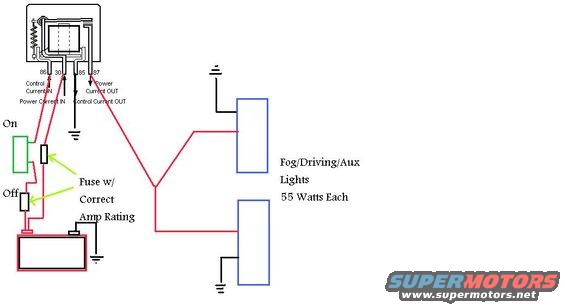
Simplified relay wiring schematic for fog/driving/auxiliary lights showing battery feed through a correctly-rated fuse, on-off switch on relay control, and two 55-watt lamps.
Part of 1987-1991 Ford Bronco Wiring Diagrams
This document is a hand-drawn digital wiring diagram showing how to wire aftermarket fog, driving, or auxiliary lights (rated 55 watts each) using a standard automotive relay. The relay is depicted with four terminals: 86 (Control Current IN), 30 (Power Current IN), 85 (Control Current OUT, which is grounded), and 87 (Power Current OUT). Power flows from the vehicle battery through an inline fuse to relay terminal 30. When the on/off switch is closed, control current flows through a second fuse and the switch to terminal 86, energizing the relay coil, whose other side (terminal 85) is grounded. Terminal 87 then feeds power out, splitting to two auxiliary lights, each of which is independently grounded. Green arrows highlight the two fuse locations with the note "Fuse w/ Correct Amp Rating," emphasizing that both the power circuit and the switch/control circuit should be fused appropriately. The diagram is generic, it contains no year, make, model, wire gauge, wire color codes, or part numbers, so it applies to virtually any 12-volt vehicle installation, including the uploader's 1988 Ford Bronco. A reader learns the correct relay pinout for auxiliary lighting, where to place fuses, and how to ground both the relay coil and the lights.
Is this accurate? Sign in to help verify it.
Frequently asked questions
- What do the relay terminals 30, 85, 86, and 87 do in this fog light wiring diagram?
- Per the diagram: 86 is Control Current IN, 30 is Power Current IN, 85 is Control Current OUT (connected to ground), and 87 is Power Current OUT feeding the lights.
- Where should fuses be placed when wiring auxiliary driving lights with a relay?
- The diagram shows two fuses, each labeled 'Fuse w/ Correct Amp Rating': one in the power feed between the battery and relay terminal 30, and one in the control circuit between the battery/switch and relay terminal 86.
- What wattage lights does this diagram cover?
- It shows Fog/Driving/Aux Lights rated at 55 Watts Each, with two lights wired in parallel from relay terminal 87.
- How are the lights and relay grounded in this setup?
- Each of the two lights has its own ground, and relay terminal 85 (Control Current OUT) is also connected to ground. The battery negative side is grounded as well.
- How does the switch control the lights in this diagram?
- The on/off switch is in the low-current control circuit feeding relay terminal 86 through a fuse; closing the switch energizes the relay, which passes battery power from terminal 30 out through terminal 87 to both lights.
Comments
More from this build







No comments yet.