Home/
Registry/
Ford/
Bronco/
1987-1991/
1987 Ford Bronco/
Photo
supermotors.net/registry/media/685447
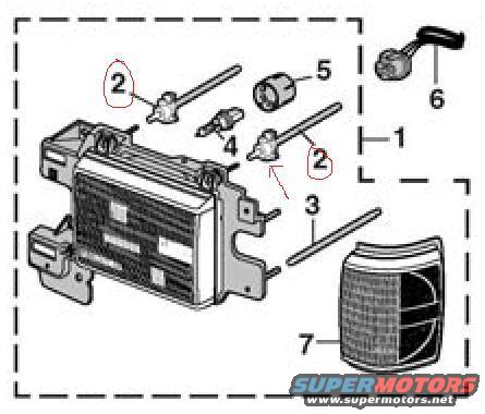
1987 Ford Bronco Headlight Assembly Exploded Parts Diagram - Callouts 1-7
Reference · 1987-1991 BroncoAll 61 exploded parts diagrams












Exploded parts breakdown of a headlight and side-marker light assembly with numbered mounting hardware.
Part of 1987-1991 Ford Bronco Exploded Parts Diagrams
This document is an exploded parts diagram showing a headlight/front lamp assembly for a vehicle, uploaded as reference for a 1987 Ford Bronco. The illustration, enclosed in a dashed border, shows a headlamp housing/bucket assembly with its mounting bracket at the left, and to the right a series of numbered components: item 1 appears to indicate the overall assembly grouping, item 2 (circled in red in two locations) points to adjuster/retainer components with long screws, item 4 shows a small bulb or socket component, item 5 shows a cylindrical grommet or bushing, item 3 indicates a long adjusting screw or rod, item 6 shows a bulb socket with pigtail wiring at the upper right, and item 7 identifies the parking/side marker lamp lens assembly at the lower right. No legend, part numbers, or descriptive text accompany the numbered callouts, so the reader must match numbers to a separate parts list (possibly on companion pages lamp.jpg or lamp2.jpg in the same album). The diagram is useful for understanding how the headlamp assembly, adjusters, grommets, socket, and corner lamp fit together and which small hardware pieces (item 2, highlighted in red) are of particular interest to the uploader.
Is this accurate? Sign in to help verify it.
Frequently asked questions
- What components are shown in this diagram?
- An exploded view of a headlight assembly including the headlamp housing/bracket, adjuster screws and retainers (item 2, circled in red), a small bulb/socket (item 4), a cylindrical bushing/grommet (item 5), an adjusting screw (item 3), a wired bulb socket (item 6), and a corner/parking lamp lens (item 7).
- Which parts are highlighted in the diagram?
- Item 2 is circled in red in two locations, pointing to the adjuster/retainer components with their long screws.
- Does the diagram include part numbers or a legend?
- No. Only numbered callouts (1 through 7) are shown; there is no legend, part numbers, or descriptive text in the image.
- How many numbered items are in this exploded view?
- Seven numbered callouts (1-7), with item 2 appearing twice.






No comments yet.