Home/
Registry/
Ford/
Bronco/
1987-1991/
1987 Ford Bronco/
Photo
supermotors.net/registry/media/702248
Ford Bronco Auxiliary Reverse Lamps Relay Wiring Diagram - Tap Methods A & B

Reference · 1987-1991 BroncoAll 175 wiring diagrams





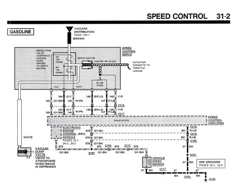
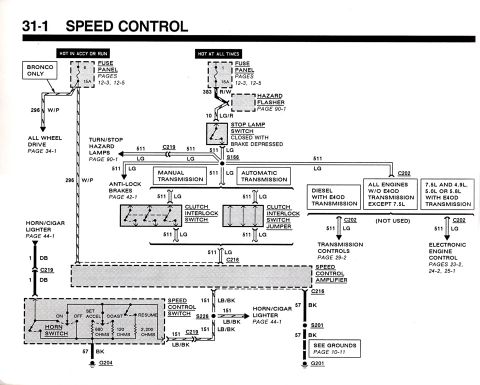










Wiring diagram for reverse lamps showing 12V fused power, switched power, a relay, and lamp connections.
Part of 1987-1991 Ford Bronco Wiring Diagrams
This document is a simple hand-drawn wiring diagram, apparently for adding or wiring auxiliary reverse lamps, uploaded to the gallery of a 1987 Ford Bronco. The top portion shows a relay (drawn as a black square) with four labeled connections: '12V Fused' power input (red wire), 'Switched Power' output (red) feeding two lamp symbols that are each grounded, a 'Powered Switch' trigger input (blue), and a 'Reverse Lamps' connection (blue) shown going to ground. The middle of the page shows a blue wire labeled 'Reverse Lamps' with a small connector or splice symbol attached beneath it. The bottom portion shows two alternative wiring/splice arrangements labeled 'A' and 'B', each depicted as a horizontal blue wire with a black connector or tap attached, 'A' shows the tap on an unbroken wire, while 'B' shows the wire with a gap (cut) at the connector. The document contains no fuse amperage values, part numbers, wire gauge specifications, or vehicle year/model identification. A reader can learn the basic relay-triggered circuit concept: fused battery power switched by a relay that is triggered from the vehicle's existing reverse lamp circuit, powering additional lamps.
Is this accurate? Sign in to help verify it.
Frequently asked questions
- How are the auxiliary reverse lamps powered in this diagram?
- A relay receives a '12V Fused' input and outputs 'Switched Power' to two lamps, each of which is grounded. The relay is triggered via a 'Powered Switch' input connected to the 'Reverse Lamps' circuit.
- What triggers the relay for the extra reverse lamps?
- The diagram shows a 'Powered Switch' input on the relay wired (in blue) to the vehicle's 'Reverse Lamps' circuit, with the other relay coil side going to ground.
- What are options A and B in the diagram?
- They show two ways of attaching a connector/tap to the reverse lamp wire: option A shows the tap on an intact wire, while option B shows the wire cut at the connector.
- Does the diagram specify fuse sizes or wire gauges?
- No. It labels the power feed only as '12V Fused' and gives no amperage ratings, wire gauges, or part numbers.






No comments yet.