SuperMotors SuperMotors SUPERMOTORS Search: try “orange Bronco on 35s”
Home/ Registry/ Ford/ Bronco/ 1987-1991/ 1987 Ford Bronco/ Photo supermotors.net/registry/media/709623

3-Position Auto/Off/On Switch Wiring Schematic - Temp Sensor & Relay Ground
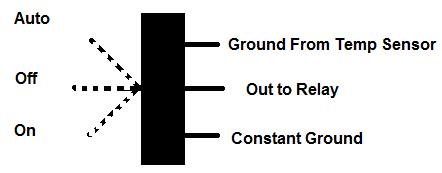
Three-position Auto/Off/On switch terminal diagram for temp sensor, relay and constant ground
Three-position Auto/Off/On switch terminal diagram for temp sensor, relay and constant groundOriginal file
Three-position Auto/Off/On switch terminal diagram for temp sensor, relay and constant ground

Reference · 1987-1991 BroncoAll 110 schematics

3-Position Auto/Off/On Switch Wiring Schematic - Temp Sensor & Relay Ground Ford 5.0 Fox Mustang Short Belt Routing Diagram - 84.5" & 70.5" vs Stock Ford Thermactor Air Bypass Valve Cutaway Diagram - Port Identification Ford Vacuum Check Valve Direction Diagram - Airflow & Black Vacuum Side Ford Thermactor Air Diverter Valve Diagram - Inlet & Outlet Port Identification Ford Idle Air Control (IAC) Valve Diagram - Cutaway Schematic & Airflow Ford Idle Air Bypass (IAB) Solenoid Cutaway Diagram - Plunger, Spring, Airflow Ford Idle Air Control (ISC-BPA) Solenoid Cutaway Schematic - Bronco IAC Valve Ford TPS Throttle Position Sensor Wiring Diagram - VREF, TP SIG, SIG RTN Colors Integral Gear Power Steering Fluid Flow Diagram - Ford Bronco Gear Box Schematic Ford Thermactor Air Control Valve & Check Valves Diagram - Rear Engine View Ford 5.0L Thermactor Secondary Air System Diagram - Air Pump & Check Valves 110schematics1987-1991 Ford Bronco More reference Ford Bronco Auxiliary Reverse Lamps Relay Wiring Diagram - Tap Methods A & BWiring diagram 1987 Ford Bronco Headlight Assembly Exploded Parts Diagram - Callouts 1-7Exploded parts Ford Canister Purge Regulator Valve (CANP 9C915) Test Procedure - Figure 11Service procedure Welder Input Data Plate - Serial JH229505, Stock 901782, 200/230/460V SpecsSpec plate Ford 5.0L/5.8L Air Throttle Body Assembly Diagram - Canister Purge Ports & TPSManual page Magnum Metropolitan Brochure - Ford Bronco/F-Series Suburban-Style ConversionBrochure Tubing Adapter Blueprint 2.00" OD x 1.375" ID x 3" - 1.125"-12 TPI RH ThreadBlueprint '89 Ford vehicle emission control information label with EEC IV/EFI timing steps and vacuum hose routingVacuum routing 1990 Ford Bronco Fuse Panel Diagram: Fuse Positions, Amps & Circuits (11-2)Fuse chart Ford V8 Intake Manifold Bolt Tightening Sequence Diagram - Stud LocationsTorque spec

Simple switch schematic showing an Auto/Off/On selector with three terminals: ground from temp sensor, output to relay, and constant ground.

Part of 1987-1991 Ford Bronco Schematics

AI caption · Photo 22 of 50

This document is a simple hand-drawn style schematic of a three-position switch, likely intended for an electric cooling fan (or similar relay-controlled accessory) wiring setup. The switch has three selectable positions shown on the left: Auto, Off, and On, each indicated with dashed arrows pointing toward the switch body. On the right side, three terminals are labeled: the top terminal connects to "Ground From Temp Sensor," the middle terminal is "Out to Relay," and the bottom terminal is "Constant Ground." From this, a reader can learn how to wire a three-position toggle switch so that in the Auto position the relay is grounded through a temperature sensor (allowing automatic operation based on temperature), in the On position the relay output is tied to constant ground (forcing the relay/accessory on), and in the Off position no ground path is provided (accessory off). The document contains no vehicle-specific information, part numbers, wire colors, fuse ratings, or dates. It appears to be one page of a multi-page set uploaded to a 1987 Ford Bronco gallery, presumably documenting an aftermarket electric fan or relay control installation.

Is this accurate? Sign in to help verify it.

Frequently asked questions

What are the three positions on the switch in this schematic?
Auto, Off, and On.
What are the three terminal connections shown on the switch?
Ground From Temp Sensor (top), Out to Relay (middle), and Constant Ground (bottom).
Which terminal goes to the relay?
The middle terminal is labeled "Out to Relay."
How does the Auto position work according to the diagram?
In Auto, the switch connects the relay output terminal to the terminal labeled "Ground From Temp Sensor," so grounding is provided through the temperature sensor.


Comments

No comments yet.

More 1987-1991 Broncos