Home/
Registry/
Ford/
Bronco/
1987-1991/
1987 Ford Bronco/
Photo
supermotors.net/registry/media/702243
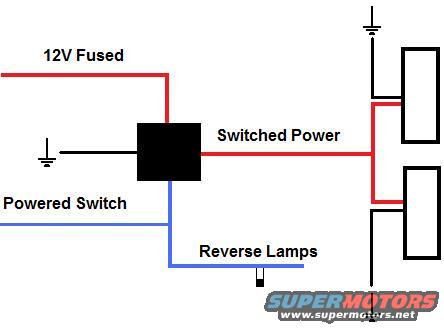
Relay Wiring Diagram for Auxiliary/Reverse Lamps - 12V Switched Power Setup
Reference · 1987-1991 BroncoAll 175 wiring diagrams





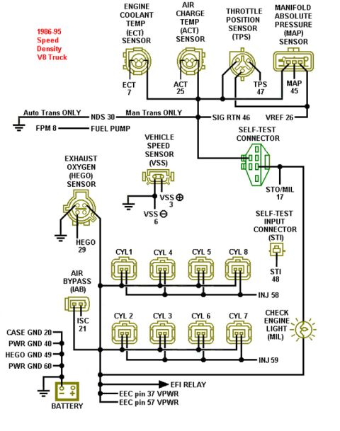
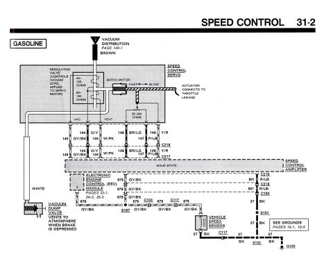
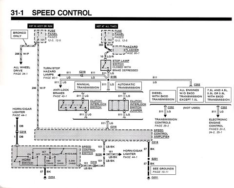










Simple relay wiring diagram for reverse lamps showing 12V fused supply, powered switch trigger, relay-switched power output to two reverse lamps, and grounds.
Part of 1987-1991 Ford Bronco Wiring Diagrams
This document is a simple hand-drawn style wiring diagram (uploaded as "lamp.jpg") showing how to wire auxiliary lamps using a relay. A black square in the center represents the relay. Power input is a red wire labeled "12V Fused" from the top left. The relay case/terminal on the left is shown grounded. The relay is triggered by a blue wire labeled "Powered Switch," which also branches to a line labeled "Reverse Lamps," indicating the trigger can come from the reverse lamp circuit so the auxiliary lamps activate with the backup lights (or via the switch). The relay output, a red wire labeled "Switched Power," runs to the right and splits to feed two lamps, each of which is independently grounded. The diagram teaches a reader the basic relay-controlled lamp circuit: fused battery power to the relay, a low-current switched trigger (switch and/or reverse lamp feed), and switched output power to two grounded lamps. No fuse amperages, wire gauges, part numbers, terminal numbers, or vehicle-specific details are given; wire colors in the drawing are red (power) and blue (trigger/switch) only. It was uploaded to a 1987 Ford Bronco gallery but the diagram itself is generic.
Is this accurate? Sign in to help verify it.
Frequently asked questions
- How are the auxiliary lamps powered in this diagram?
- A red "12V Fused" wire feeds the relay, and the relay's red "Switched Power" output splits to feed two lamps, each with its own ground.
- What triggers the relay?
- A blue wire labeled "Powered Switch" triggers the relay; it also connects to a branch labeled "Reverse Lamps," so the trigger ties into the reverse lamp circuit.
- How many lamps does this diagram show being wired?
- Two lamps, wired in parallel off the switched power output, each grounded separately.
- Does the diagram specify fuse size or wire gauge?
- No. It only labels "12V Fused," "Switched Power," "Powered Switch," and "Reverse Lamps", no amp ratings, gauges, or part numbers are shown.






No comments yet.