Home/
Registry/
Ford/
Bronco/
1978-1979/
“buyers guide”/
Photo
supermotors.net/registry/media/756762
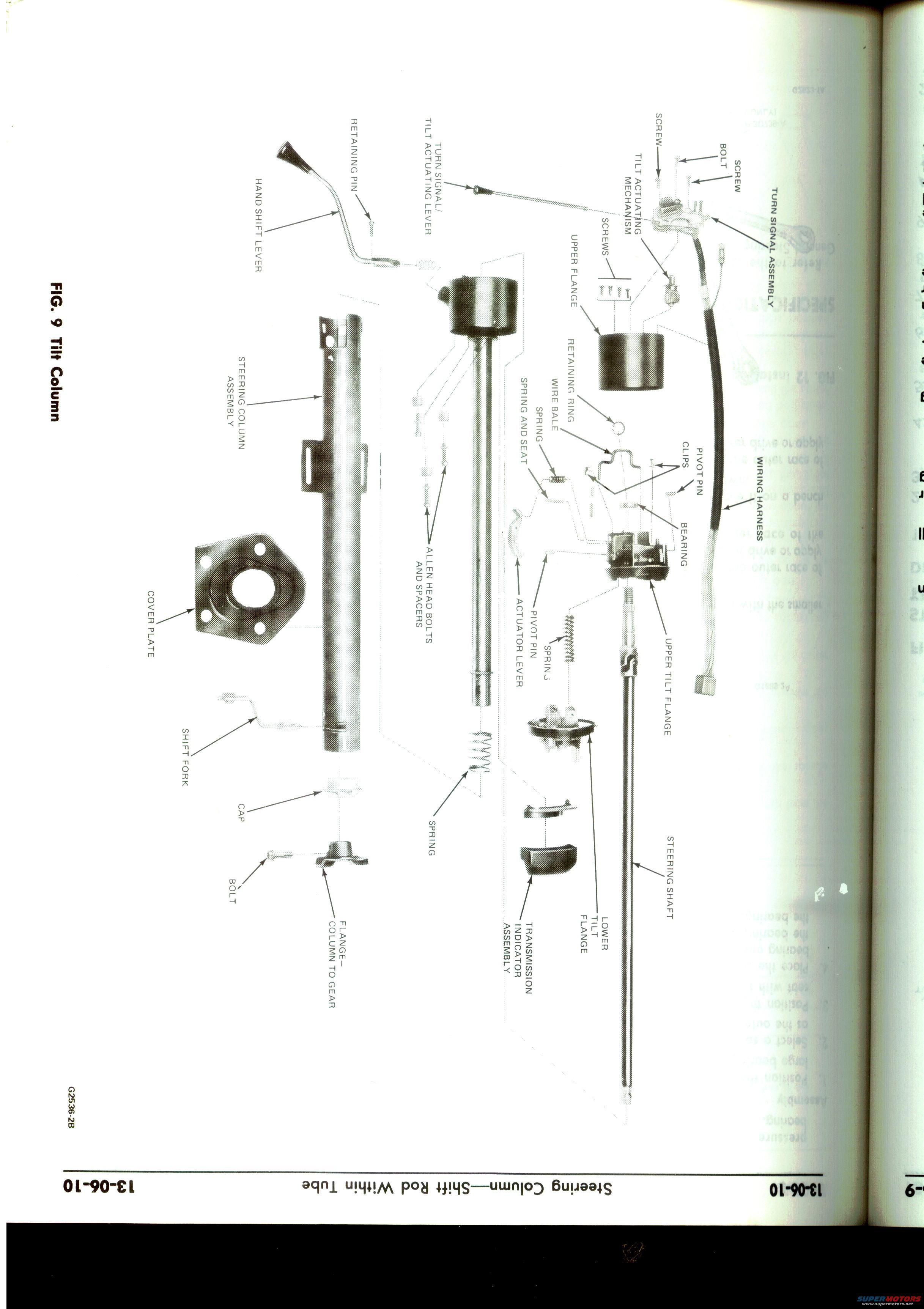
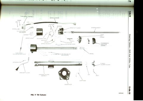
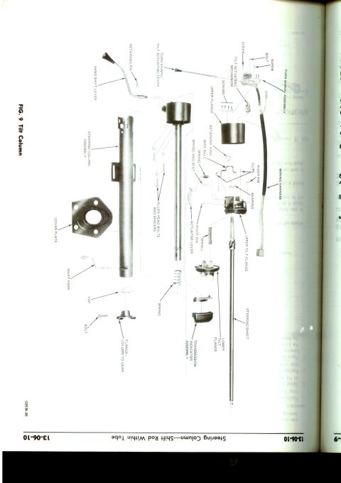
1979 Ford Bronco Tilt Steering Column Exploded Diagram - Fig. 9, Page 13-06-10
Reference · 1978-1979 BroncoAll 79 exploded parts diagrams


Exploded parts diagram of a tilt steering column and shift rod assembly from a service manual.
Part of 1978-1979 Ford Bronco Exploded Parts Diagrams
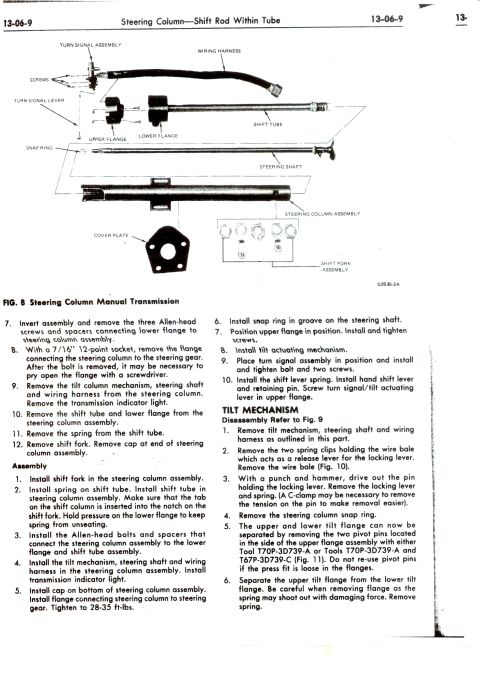
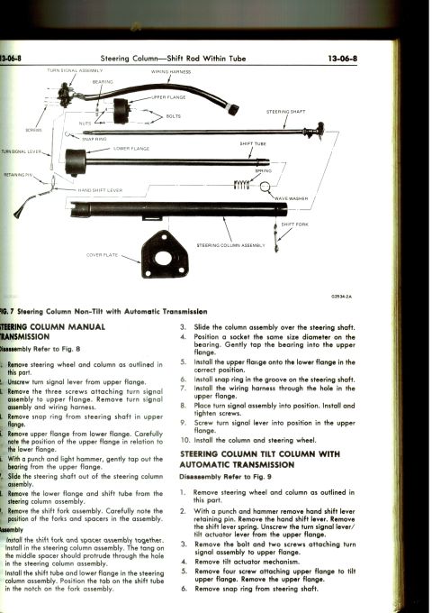
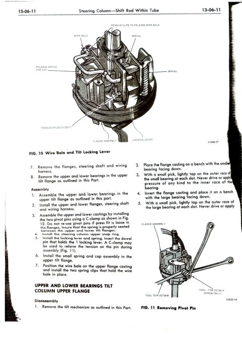
This is a scanned page (13-06-10) from a Ford service manual section titled "Steering Column: Shift Rod Within Tube." The page contains FIG. 9, a full-page exploded parts diagram of a tilt steering column assembly with a column-mounted (hand) shift lever. Each component is identified by a callout label, showing the disassembly relationship of parts including the hand shift lever, retaining pin, turn signal/tilt actuating lever, tilt actuating mechanism, turn signal assembly with wiring harness, upper flange, steering column assembly (outer tube), retaining ring, wire bale, springs, spring and seat, pivot pins, clips, bearing, Allen head bolts and spacers, cover plate, actuator lever, upper and lower tilt flanges, shift fork, cap, flange (column to gear), transmission indicator assembly, and steering shaft. The illustration reference number is G2536-2B. No part numbers, torque specifications, or model-year applicability text appear on this page; it serves purely as a visual reference for identifying components and their order of assembly when servicing, disassembling, or rebuilding a tilt steering column with the shift rod inside the tube. It is one page of a multi-page steering column section (adjacent pages 13-06-07 through 13-06-11 are in the same set).
Is this accurate? Sign in to help verify it.
Frequently asked questions
- What does Figure 9 on page 13-06-10 show?
- It shows an exploded view of the tilt steering column (shift rod within tube), labeling every major component from the hand shift lever down to the steering shaft.
- What parts make up the tilt actuating system in this diagram?
- The diagram labels a turn signal/tilt actuating lever, tilt actuating mechanism, actuator lever, pivot pins, springs, spring and seat, wire bale, retaining ring, and upper and lower tilt flanges.
- Does this diagram show the turn signal components?
- Yes, it labels the turn signal assembly with its wiring harness, mounting screws, and the combined turn signal/tilt actuating lever.
- What fasteners are identified in the exploded view?
- Screws, bolts, Allen head bolts and spacers, a retaining pin, retaining ring, clips, and a bolt for the flange (column to gear).
- Are torque specs or part numbers included on this page?
- No. The page is an exploded illustration with component names only; the only reference number shown is the illustration code G2536-2B.






No comments yet.