Home/
Registry/
Ford/
Bronco/
1978-1979/
“buyers guide”/
Photo
supermotors.net/registry/media/756764
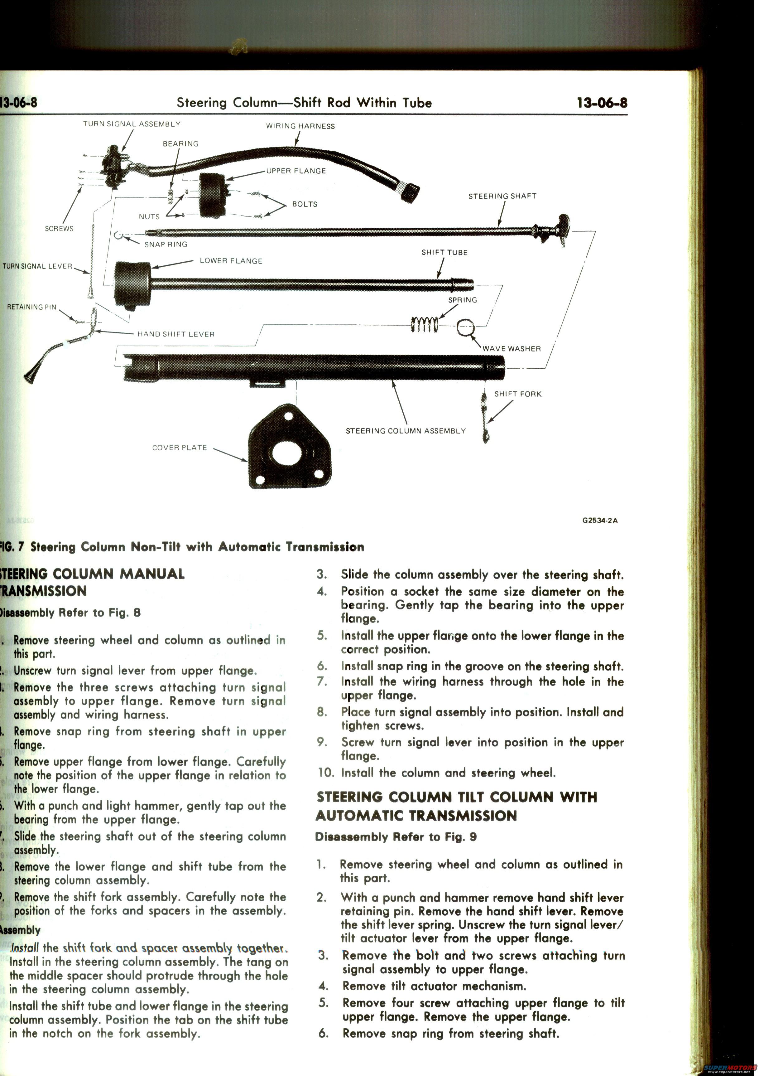
Ford Bronco Steering Column Exploded Diagram & Disassembly - Shop Manual 13-06-8
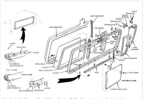
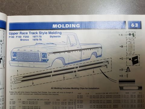
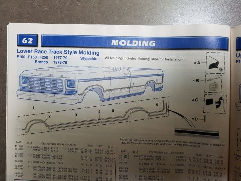
Reference · 1978-1979 BroncoAll 79 exploded parts diagrams
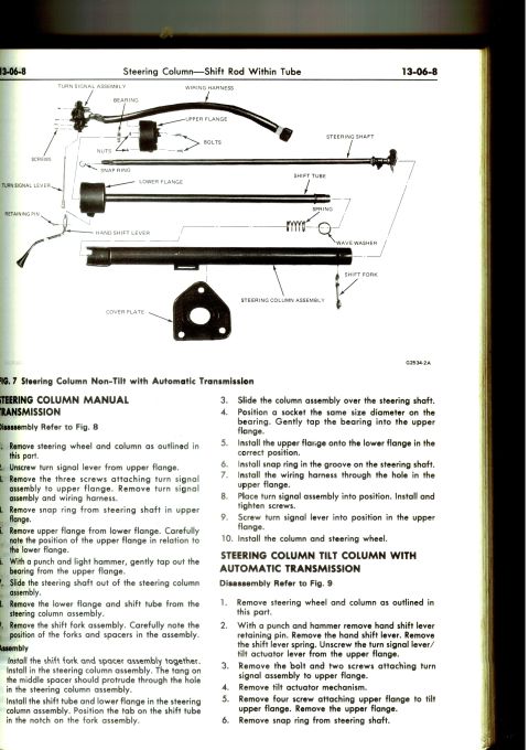


Ford steering column service (13-06-8, Fig.7): exploded view of non-tilt column with manual transmission showing turn-signal assembly, flanges, shift tube, fork and wave washer plus assembly steps.
Part of 1978-1979 Ford Bronco Exploded Parts Diagrams
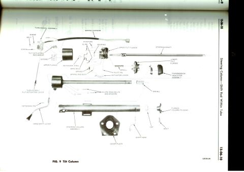
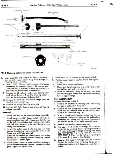
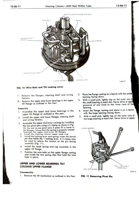
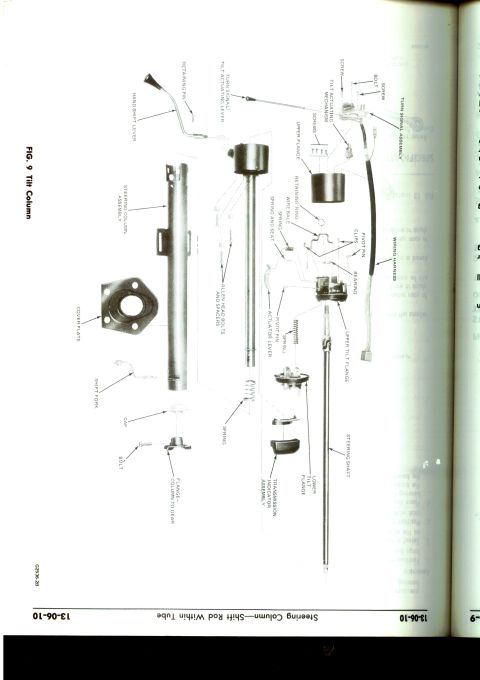
This is page 13-06-8 of a Ford shop manual section titled "Steering Column: Shift Rod Within Tube." The top half of the page contains Fig. 7, an exploded parts diagram of a non-tilt steering column used with an automatic transmission (illustration reference G2534-2A). Labeled components include the turn signal assembly, wiring harness, bearing, upper and lower flanges, bolts, nuts, screws, steering shaft, snap ring, shift tube, turn signal lever, spring, retaining pin, hand shift lever, wave washer, shift fork, steering column assembly, and cover plate. The lower half provides step-by-step service procedures: a 9-step disassembly and 10-step assembly procedure for the steering column with manual transmission (referencing Fig. 8), covering removal of the steering wheel, turn signal components, snap ring, flanges, bearing, steering shaft, shift tube, and shift fork. The page then begins the disassembly procedure (steps 1-6, referencing Fig. 9) for a tilt steering column with automatic transmission, including removal of the hand shift lever retaining pin, tilt actuator mechanism, upper flange screws, and snap ring. Readers can use this page to identify column parts and follow the correct order for teardown and reassembly of column-shift steering columns.
Is this accurate? Sign in to help verify it.
Frequently asked questions
- What does Fig. 7 on page 13-06-8 show?
- Fig. 7 is an exploded view of the non-tilt steering column with automatic transmission, labeling parts such as the turn signal assembly, wiring harness, bearing, upper and lower flanges, steering shaft, snap ring, shift tube, spring, wave washer, shift fork, cover plate, and the steering column assembly (illustration reference G2534-2A).
- How do you remove the bearing from the upper flange during disassembly?
- With a punch and light hammer, gently tap the bearing out of the upper flange (step 6 of the manual transmission disassembly procedure).
- How is the bearing reinstalled into the upper flange?
- Position a socket of the same size diameter on the bearing and gently tap the bearing into the upper flange (assembly step 4).
- What are the first steps to disassemble a tilt column with automatic transmission?
- Remove the steering wheel and column, then use a punch and hammer to remove the hand shift lever retaining pin, remove the hand shift lever and shift lever spring, unscrew the turn signal lever/tilt actuator lever from the upper flange, then remove the bolt and two screws holding the turn signal assembly, remove the tilt actuator mechanism, remove four screws attaching the upper flange, and remove the snap ring from the steering shaft.
- What must you note when removing the shift fork assembly?
- Carefully note the position of the forks and spacers in the assembly so they can be reinstalled correctly; on assembly, the tang on the middle spacer should protrude through the hole in the steering column assembly.






No comments yet.