Home/
Registry/
Ford/
Bronco/
1992-1996/
“Dead reckoning”/
Photo
supermotors.net/registry/media/790643
Auxiliary Light Relay Wiring Diagram - Switch, Fuse & Relay Hookup (Ford Bronco)
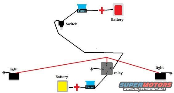
Wiring diagram showing a switch, fuses, battery, relay, and two light circuits with wire runs.
This document is a simple hand-drawn (MS Paint style) auxiliary lighting wiring diagram, uploaded to a 1995 Ford Bronco gallery under the filename "lights.jpg." It illustrates how to wire two auxiliary lights through a standard automotive relay. The relay is drawn as a gray box with four terminals labeled 7, 6, 5, and 0 (apparently truncated versions of standard relay pin numbers). The control circuit runs from the battery positive terminal through a fuse to a toggle switch, then to relay terminal 5; terminal 6 is grounded. The power (load) circuit runs from the battery positive through a second fuse to relay terminal 0, and terminal 7 feeds red wires out to two lights, each of which is grounded independently. The diagram shows two battery icons for drawing clarity, both with fuses on their positive leads. No wire gauges, fuse amperage ratings, part numbers, or vehicle-specific information are given. A reader can learn the basic topology for relay-controlled off-road/auxiliary light installation: fused switched trigger circuit, fused main power feed, relay-switched output to the lamps, and grounding points for the relay coil and each light.
Is this accurate? Sign in to help verify it.
Frequently asked questions
- How is the switch wired in this auxiliary light diagram?
- The switch is fed from the battery positive terminal through a fuse, and its output wire runs to relay terminal 5, acting as the relay trigger.
- Which relay terminal powers the lights?
- Terminal 7 of the relay feeds red wires out to both lights; terminal 0 receives fused battery power, terminal 5 is the switched trigger, and terminal 6 goes to ground.
- Are the battery feeds fused in this diagram?
- Yes, both battery positive connections shown (one to the switch circuit and one to relay terminal 0) pass through a fuse.
- How are the lights grounded?
- Each light is shown with its own ground symbol, meaning each lamp is grounded individually at its location.
- Does the diagram specify fuse amperage or wire gauge?
- No. The diagram labels only the components (Fuse, Battery, Switch, relay, light) and relay terminals 7, 6, 5, 0; no amp ratings, wire gauges, or part numbers are given.
Comments
More from this build












No comments yet.