Home/
Registry/
Ford/
Bronco/
1992-1996/
1995 Ford Bronco/
Photo
supermotors.net/registry/media/795360
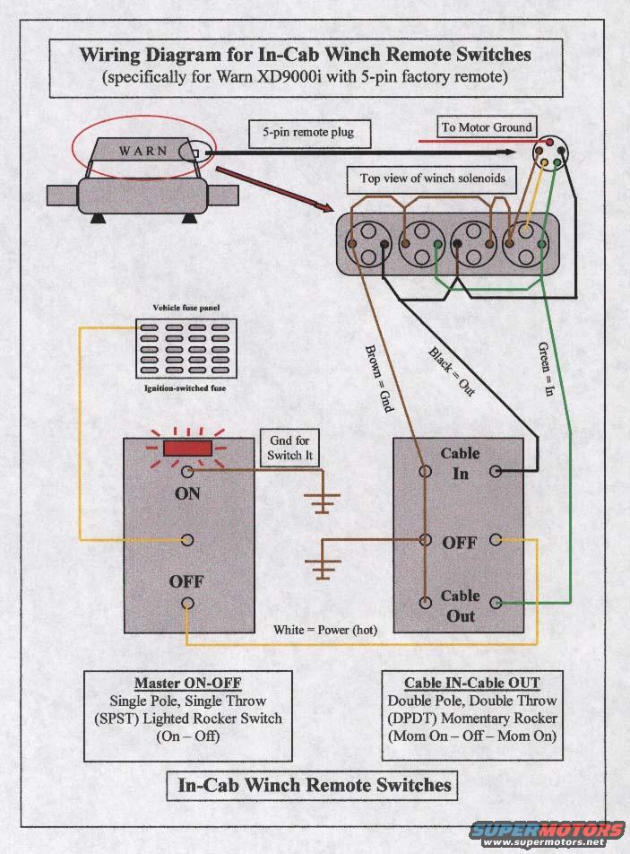
Warn XD9000i In-Cab Winch Remote Switch Wiring Diagram (5-Pin Remote)
Reference · 1992-1996 BroncoAll 411 wiring diagrams


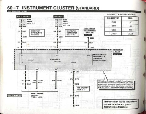
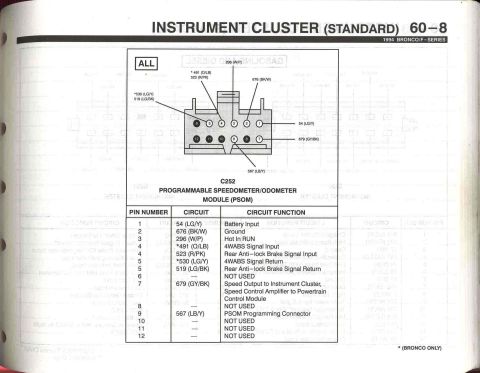
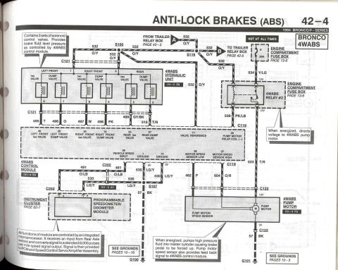
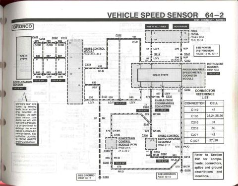









Wiring diagram for in-cab winch remote switches showing the 5-pin remote, solenoids, and master and cable-in/cable-out rocker switches.
Part of 1992-1996 Ford Bronco Wiring Diagrams
This document is a hand-assembled wiring diagram for adding in-cab remote switches to a Warn XD9000i winch equipped with a 5-pin factory remote plug. It shows the winch mounted on the front of a vehicle, the 5-pin remote plug location, and a top view of the winch solenoid pack with the connector wiring routed to the motor ground. Four wire color codes are defined: Brown = Ground, Black = Out (cable out), Green = In (cable in), and White = Power (hot). Power for the circuit is taken from an ignition-switched fuse in the vehicle fuse panel. Two in-cab switches are illustrated with terminal connections: a Master ON-OFF switch, which is a Single Pole, Single Throw (SPST) lighted rocker switch (On-Off) with a ground connection for its indicator light, and a Cable IN-Cable OUT switch, a Double Pole, Double Throw (DPDT) momentary rocker (Mom On: Off, Mom On) with terminals labeled Cable In, OFF, and Cable Out. A reader can learn how to wire these two rocker switches to the winch's 5-pin remote connector so the winch can be operated from inside the cab, including which wire colors go to which switch terminals and where to source power and ground.
Is this accurate? Sign in to help verify it.
Frequently asked questions
- What winch does this in-cab remote switch wiring diagram apply to?
- It is specifically for the Warn XD9000i winch with the 5-pin factory remote plug.
- What wire colors are used and what do they do?
- Brown = Ground, Black = Out (cable out), Green = In (cable in), and White = Power (hot).
- What type of switches are needed for this in-cab winch control setup?
- A Master ON-OFF switch that is a Single Pole, Single Throw (SPST) lighted rocker (On-Off), and a Cable IN-Cable OUT switch that is a Double Pole, Double Throw (DPDT) momentary rocker (Mom On: Off, Mom On).
- Where does the switch circuit get its power?
- From an ignition-switched fuse in the vehicle fuse panel, carried on the white (Power/hot) wire.
- Where does the winch remote circuit get its ground?
- The brown ground wire runs to the motor ground at the winch, and a separate ground is shown for the lighted switch (labeled 'Gnd for Switch It').






No comments yet.